How should the i7 and CFS lite be positioned?
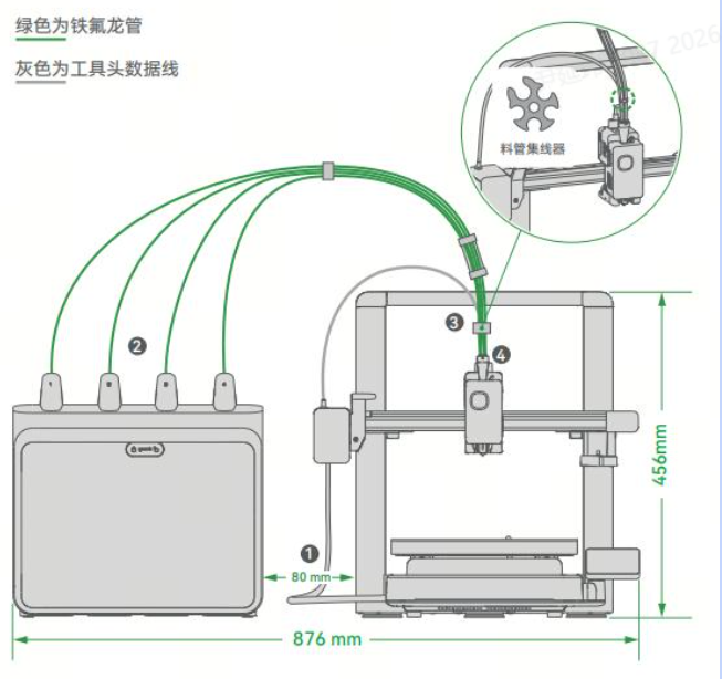
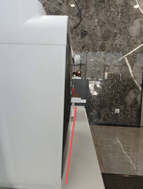
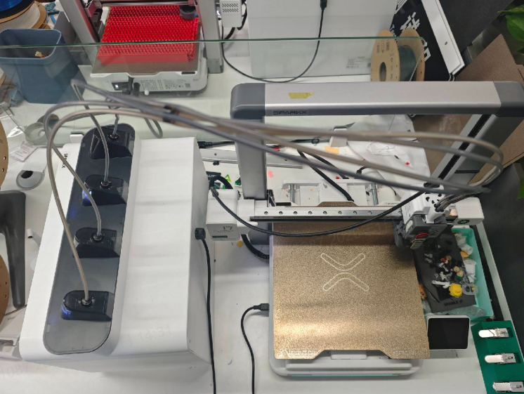
It is recommended to position the i7 and CFS lite as shown , leaving sufficient space between them. Keep a distance of approximately 8 cm from the gantry frame and about 2 cm from the left side of the X-axis.
In addition, do not place the CFS lite too far back. It is recommended to align the front of the CFS lite with the front of the i7, or position it centered relative to the printer.
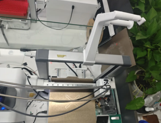
If your available space is limited, you may place the CFS lite sideways next to the printer. Make sure the orientation is correct, with the access door facing outward.
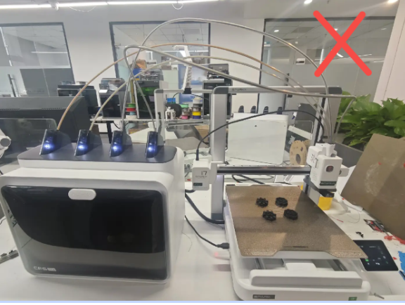
Incorrect Placement
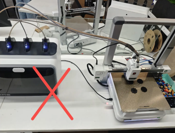
CFS Lite is positioned too far from the printer. 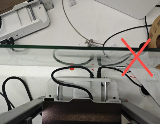
No clearance is left behind the printer.
PTFE Tube Hubs not installed 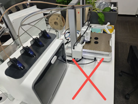
CFS Lite is placed too far toward the rear relative to the printer.
Not using the spool holder means installing the spool holder on the gantry
How should the PTFE tubes be routed to reduce resistance during filament loading and unloading?
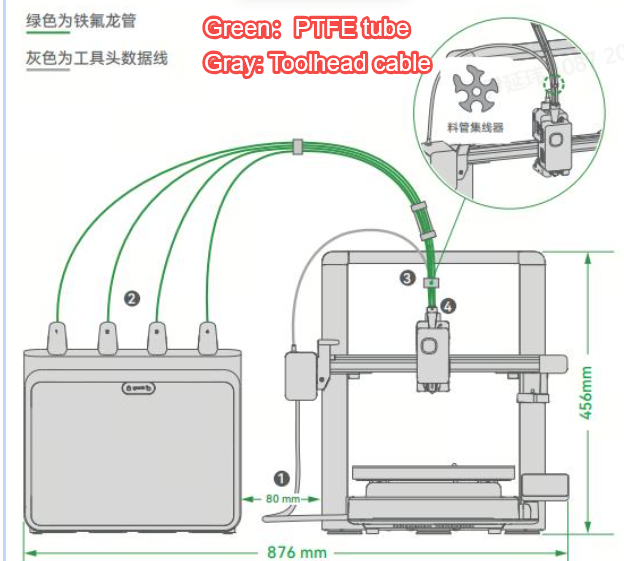
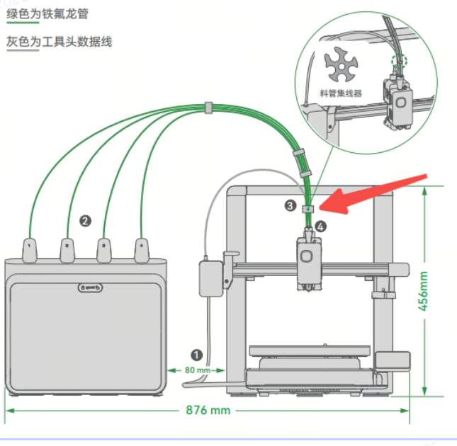
- All four PTFE tubes are 98 cm in length.
- The recommended distance between the i7 and the CFS lite is 8 cm (measured from the gantry frame, or 2 cm from the leftmost side of the X-axis), as shown. Placing the CFS lite too far away may increase resistance during filament loading and unloading.
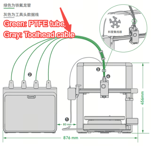
- To reduce filament resistance, three different PTEF tube hubs are used to help guide and maintain the proper shape of the PTFE tubes.Please install each hub as shown:
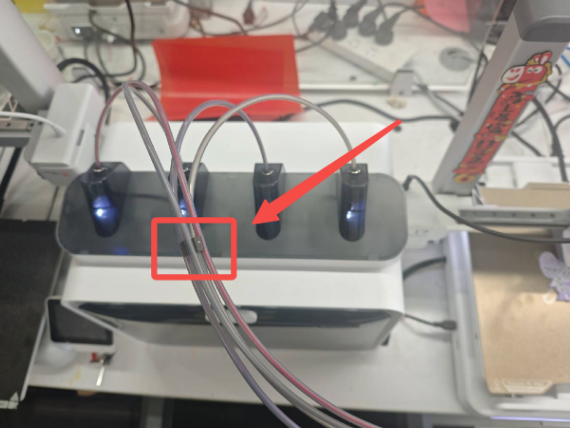
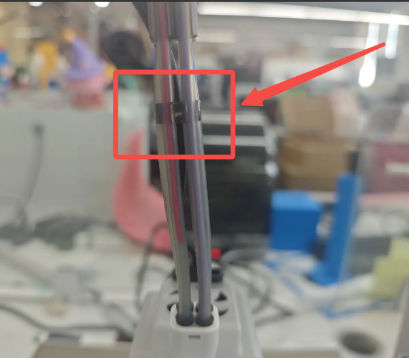
4-Port Hub (Short): Install near the center position.
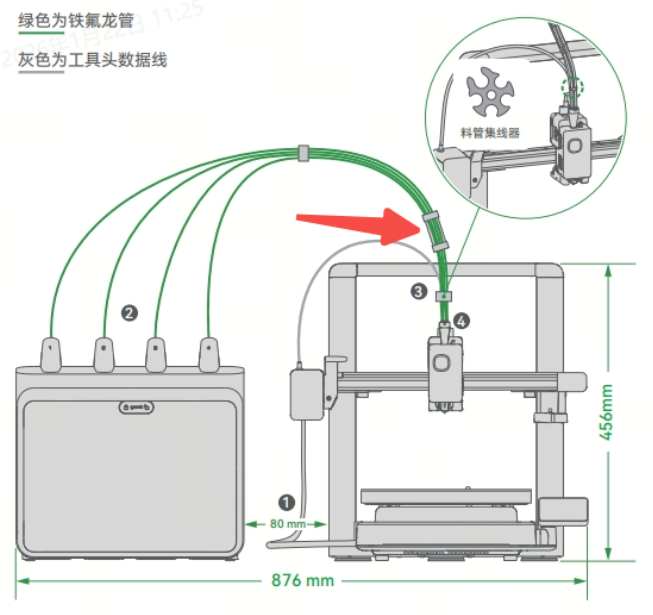
4-Port Hub (Long): This hub is factory-installed and fixed in position, approximately 8 cm from one end of the PTFE tubes.
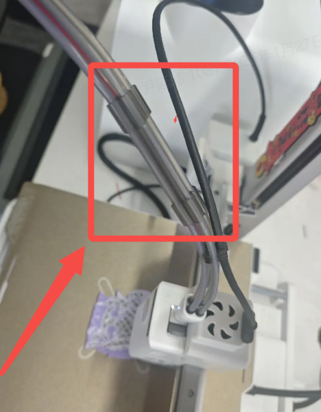
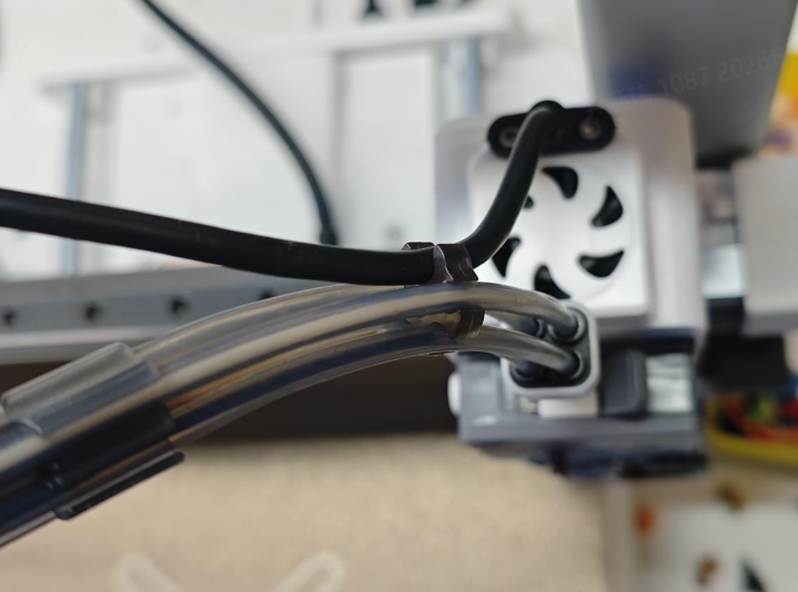
5-Port Hub: Install between the i7 toolhead 5-way connector and the long 4-port hub. Position it closer to the long 4-port hub during installation. The larger opening should face the rear of the i7 to allow the toolhead data cable to be clipped into the hub. Note: Make sure the toolhead data cable is secured inside the hub to prevent damage during operation.
How much space is required for the i7 Color Combo (i7 + CFS Lite)?
To ensure convenient and safe use of the i7 Color Combo, prepare an installation space with a width of 876 mm and a height of 550 mm (the height includes the PTFE tubes).
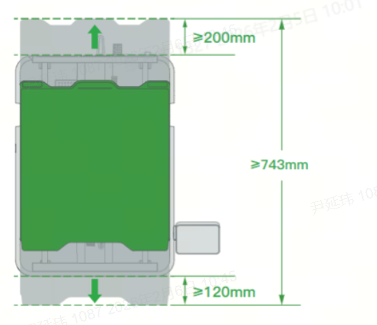
Because the heated bed of the i7 moves back and forth, the required motion clearance is approximately 100 mm + 110 mm + 423 mm = 633 mm.
However, to prevent the heated bed cable from colliding with objects behind the printer, and to avoid contact with the user when the bed moves to the frontmost position, we recommend leaving additional clearance:
200 mm behind the i7
120 mm in front of the i7
As a result, the total recommended safe depth is 200 mm + 120 mm + 423 mm = 743 mm.
Why are the PTFE tubes I received not all the same length? The Quick Start Guide also mentions PTFE tubes of different lengths.
Initially, to ensure optimal filament feeding resistance, we did use PTFE tubes of different lengths.
However, for the sake of ease of use, we have optimized the CFS Lite to reduce feeding resistance, extended the PTFE tubes, and further improved the stability of filament loading and unloading. At the same time, we standardized the PTFE tubes to be the same length, making installation more convenient for you.
If the PTFE tubes you received are of different lengths, please note the following:
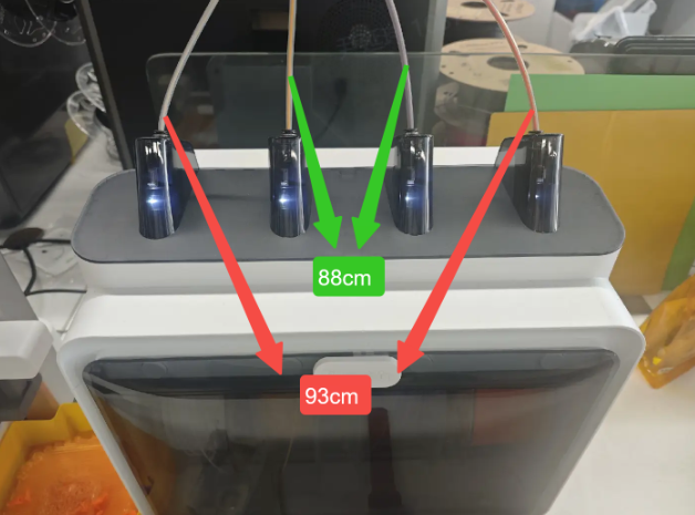
Your PTFE tubes come in two lengths: 93 mm × 2 tubes and 88 mm × 2 tubes.
When inserting the PTFE tubes into the CFS lite , make sure to install the longer tubes (93 mm) in the left and right channels, and the shorter tubes (88 mm) in the middle channels.
You may also choose to replace all four tubes with 98 mm tubes and follow the instructions in this guide.
Apart from the PTFE tube lengths, all other installation steps and precautions remain the same. You can follow this guide with confidence.