Bagged a light bar for a fiver less than the Creality site. Its has just been delivered, read the manual, tells me very little. Went on Youtube and found a vid, strip down the Z frame, remove Z frame from base, undo base, feed wires through extrusion and screw into motherboard powersupply, reassemble in reverse order, screw Z frame back together with new bracket and light assembly. This is going to be fun.
I might do this on the SE too but I think I need to file some grooves in the extrusion to clear the new wires, might as well fit a filament run-out sensor too as that will need a little groove for the wires.
1 Like
Sounds like a pretty cool project.
I’m considering a light kit  upgrade for my K1 Max here. Not really brave enough as you are to do surgery on it yet though…
I might just wind up the missus and carry out this surgery on the kitchen table rather than my dusty shed, for added excitement I might leave it plugged in too…kidding about leaving it plugged in. 
Living dangerously there… 
In the video they are having to double up with other wires from the power supply…
On your machine is it the same or are there any empty slots…?
I’m guessing there is enough extra power for the LED light bar and doesn’t affect the machine…?
Maybe some pics if you have a chance.
I should imagine the installation is identical on the 2 machines, same chassis (same moulding, they didn’t bother covering unused USB slots), same gantry. Probably a different mobo in addition to the linear rail and uprated hotend/extruder.
Got a lightbar on the Ender 5+ that just plugs into USB, I’m sure there is enough juice to run a lightbar in addition to the Nebula camera that is already fitted. Be a bit miffed if I could only run one and not the other at any given time.
Interesting that the written instructions indicate that there is a knock out point in the chassis to pass the wires through and then connect to the motherboard, problem is the wires are exposed right near the Z leadscrew on the right, they are only very fine wires so that is too risky so I am going to follow the youtube build. Won’t be tonight as it is lashing it down with rain and I don’t fancy bringing the printer up the shed to the house in a rainstorm.
Hi
I have recently fitted the lightbar and the cabling is really easy on the SE version (possibly the KE too).
Look behind the upright gantry extrusion and either side you will see a groove running down. If you ensure there are no twists in the wire it will snugly fit into this grove and be safe and completely out of sight.
I did use the knockout panel in the base and the wire does not seem to go anywhere near the moving parts.
A really good addition to the printer.
Did you plug the hole back up to stop bits of filament or other foreign bodies from falling in? I’ll probably route the wires alongside the runout sensor wires, the knockout hole is already there and covered by the extrusion. The KE is in the shed/workshop so subject to all sorts of swarf/dust/errant screws.
Hi
I did not plug the the hole up, it is under the bed on the SE and quite small so I will just open the base a couple of times a year and clean it out
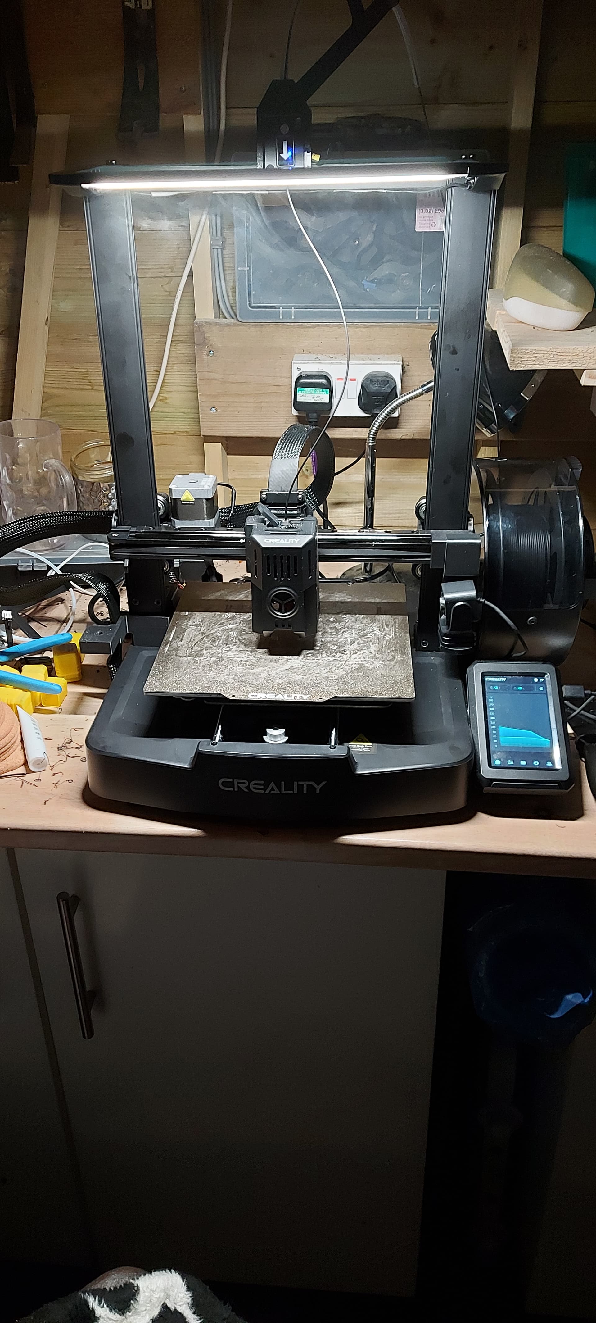
Its in the same place on the KE too, same moulding on both models. It has stopped raining long enough to retrieve the printer from the shed, pizza ordered, let surgery commence.
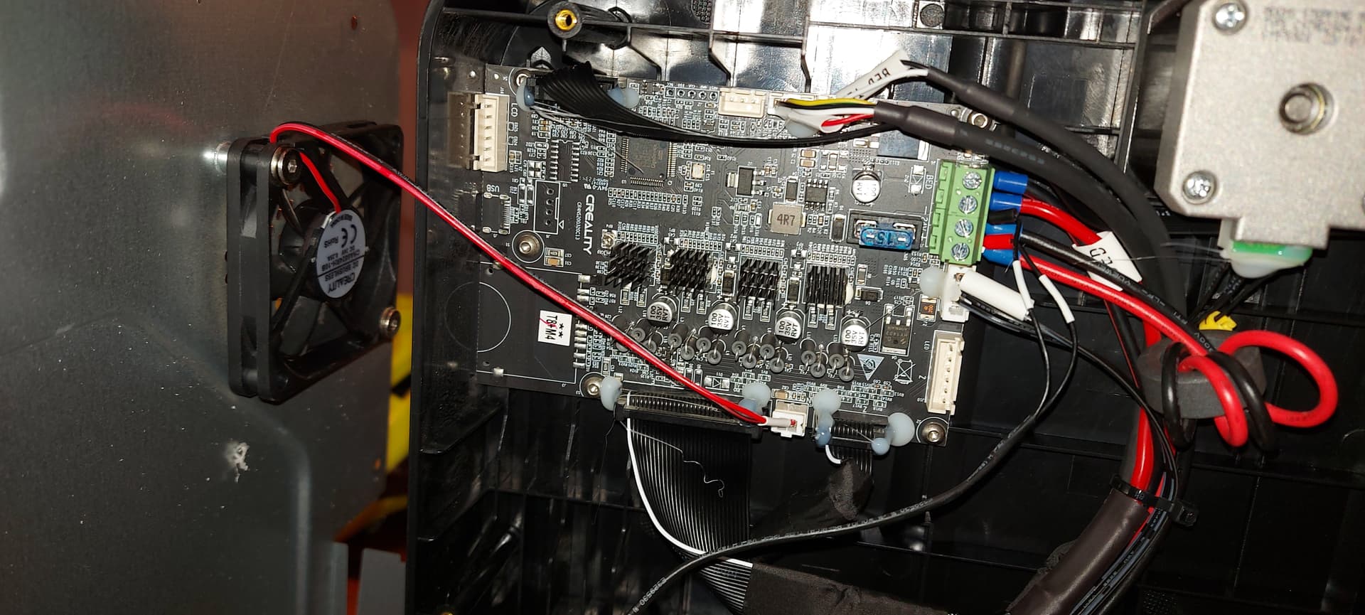
Yes I know I used glue sticks, shoot me, humidity is mental at the moment, 3 days of rain in woodland. Surprised it still works. First pic is wiring into the motherboard. I shall compare and contrast with an SE mobo soon.
1 Like
Nice…! That really lights things up… 
And this is easier than just buying a small LED kit and making something up yourself. You have a 3D printer don’t you.
Looks good and I’m glad you are pleased with the result.
No not easier at all but it was only 20 quid and I have plenty of other projects to do.
So i just got the light bar for my ke. After putting it together i found 2 washers and I am not sure where they go. I found them when i removed the gantry. Can anyone help?
Look behind the upright gantry extrusion and either side you will see a groove running down. If you ensure there are no twists in the wire it will snugly fit into this grove and be safe and completely out of sight.
This was the quickest and easiest. I was looking around for a groove and had been considering one, so good to know this was tried. Worked great for me. Had to remove the outside z-axis roller to get the wires through. Flattened them into the groove and then got a washer and ‘rolled’ it along to really make it flush - didn’t take much pressure.
Thanks for the tip!
I did use the knockout panel in the base and the wire does not seem to go anywhere near the moving parts.
Did this too. Stuck a small square of black electrical tape to cover it for now and it’s not really noticeable. I will probably sort out a grommet or something later.