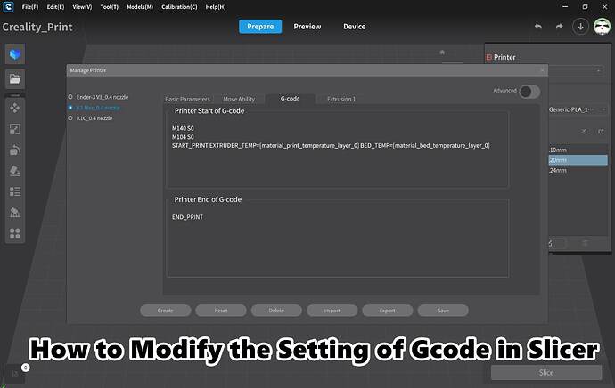
The crucial element for achieving perfect 3D printing results lies in understanding ‘How to Modify the Setting of Gcode in Slicer’ software.
This article aims to provide you with an understanding of what G-Code is, how to write a G-Code script, and more importantly, how to adjust it using an array of slicers like Prusa Slicer, Cura Slicer, and Creality Slicer.
- What is G-Code?
- Crafting a G-Code Script: The Fundamentals
- How to Modify the Setting of Gcode in Slicers
- Common G-Code Commands
What is G-Code?
Veering away from the jargon associated, let’s simplify what G-Code is. At its core, it’s a programming language for CNC machines, employed in computer-aided manufacturing. G-Code commands act as detailed choreography directing the movement of the machine’s tool.
In the context of 3D printing, “slicing” an object for printing automatically generates G-Code. The slicer software translates the 3D model into a sequence of movements in a language the printer understands— G-Code.
Crafting a G-Code Script: The Fundamentals
Writing a G-Code script requires no fancy software, just a basic text editor. Each line in the G-Code script delivers a unique instruction to the 3D printer. The process involves penning the command reference, the parameters relating to it (if any), and to explain in detail, we might add comments prefixed with a semicolon.
To start, we annotate the code’s purpose through a comment line. This sets the context and makes it easier for others (or your future self) to understand. Then we utilize the G90 command which institutes absolute positioning — a fundamental setting wherein the printer calculates every movement from a consistent commencement point.
Next, we bring into play the M117 command, which manifests a message on the Ender 2 Pro’s LCD screen. We add a brief pause or dwell in the script (command G4) to give the user time to comprehend the displayed message.
After pausing, we ask the printer to heat the print bed to 60 degrees Celsius (command M190). The script hangs at this juncture until the specified temperature is achieved. We also direct the printer to ‘home’ all its axes using the G28 command ensuring the print head starts from a known location.
The script continues by setting the movement speed at 1500mm per minute. This speed uniformity ensures that both the bed and the hot end are synchronous. If necessary, this speed could be increased up to 3000mm per minute though it’s advisable to start slow to allow reactive time for any issues.
We then lift the Z-axis by 8mm (command G1) to make sure the nozzle doesn’t collide with the print bed. Afterward, the script commands the nozzle to move to specific X and Y positions, aiming precisely above the front left bed adjustment wheel.
Next, an instruction for users to level the bed gets printed on the LCD (M117). Afterward, M0 command allows the script to pause and waits for the user’s input. However, please note that this command doesn’t work on all 3D printers. If this is the case, you can replace it with G4 and manipulate the wait time accordingly.
This sequence of the lifting nozzle, moving to the next position, printing instruction, and waiting for user input gets repeated for all four bed adjustment wheel positions.
Finally, all axes are ‘homed’ again (G28), and a “Bed leveling completed” message is printed on the LCD screen (M117).
This entire code gets saved as ‘Ender2-Pro-Test.gcode’ on a micro SD card and inserted into the printer. Using the control dial on the printer, attach the card, choose ‘Print from Card’, and finally select ‘Ender2-Pro-Test.gcode’. Then, select ‘Print’, and the printer will run this entire G-Code script in a semi-autonomous manner for bed leveling.
; Ender 2 Pro Example Control G-Code

G90; Absolute positioning
M117 Tom's Hardware; Prints the string to the LCD screen
G4 P3000; Wait for 3 seconds
M117 Heating bed; Prints the string to the LCD screen
G4 P1000; Wait for 1 second
M190 S60; Set the bed temperature to 60C and wait until it hits that temperature
G28; Home all axis
G1 F1500; Set Feedrate (tool movement) to 1500 mm/min
G1 Z8; Lift Z Axis 8mm
G1 X28 Y35; Move to position 1
M117 Level the bed #1
M0; Stop, wait for user input
G1 Z8 ; Lift Z Axis 8mm
G1 X140 Y35; Move to position 2
M117 Level the bed #2
M0; Stop, wait for user input
G1 Z8 ; Lift Z axis
G1 X140 Y130; Move to position 3
M117 Level the bed #3
M0; Stop, wait for user input
G1 Z8; Lift Z axis
G1 X28 Y130; Move to position 4
M117 Level the bed #4
M0; Stop, wait for user input
G28; Home all axis
M117 Complete; Bed leveling is completed
This comprehensive guide into writing G-Code for bed-leveling illumines how user contributions refine any 3D print job. While we based this tutorial on the Ender 2 Pro, remember that it may require alterations based on the uniqueness of your 3D printer model.
How to Modify the Setting of Gcode in Slicers
1. Creality Slicer
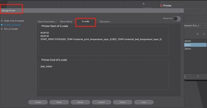
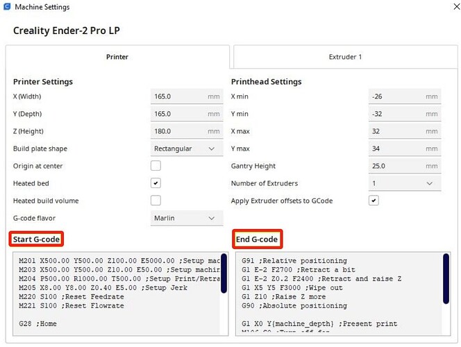
In the Creality Slicer, modifications are straightforward. Users must first add their printer and then proceed to ‘Settings > Printer > Manage Printers’, revealing the ‘Machine Settings’ tab.
Within this headquarters, users can engineer the start and end G-Code sequences to suit their needs for 3D printing.
2. Prusa Slicer
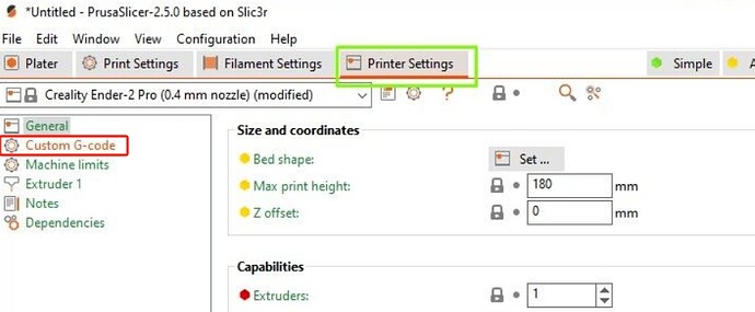
Prusa Slicer allows for seamless G-Code modification. Navigate to ‘Printer Settings’ and click on ‘Expert’. Herein locate the ‘Custom G-Code’, where you can add instructions for the start and end of a print.
Consequently, these instructions will apply to every print that you slice using Prusa Slicer, providing more refined control over your prints.
3. Cura Slicer
The road to adjusting G-Code in Cura Slicer is through ‘Settings >> Printer >> Manage Printers’, subsequently clicking on ‘Machine Settings’.
This sub-section allows for the direct editing of printer start and end G-Code. Additionally, you can modify the G-Code for the extruder by accessing ‘Extruder 1’ settings.
Common G-Code Commands
Although G-Code boasts an extensive vocabulary, certain commands frequently recur. Ever-present commands like G1 enact linear moves, while G4 inserts pauses. More commands set units of measurement, prepare axes and display messages on your printer display, assisting your understanding of G-Code alongside your growing print prowess.
| Command | Description | Example |
|---|---|---|
| G0 | Rapid movement | G0 X50 Y25 Z15 |
| G1 | Linear movement | G1 X30 Y20 F1200 |
| G2 | Clockwise arc | G2 X50 Y25 I20 J-10 |
| G3 | Counterclockwise arc | G3 X60 Y30 I15 J-5 |
| G4 | Dwell (pause) | G4 P1000 |
| G20 | Set units to inches | G20 |
| G21 | Set units to millimeters | G21 |
| G28 | Home all axes or specific axes | G28 or G28 X Y |
| G90 | Set absolute positioning | G90 |
| G91 | Set position | G92 E0 |
| M82 | Set extruder to absolute mode | M82 |
| M83 | Set extruder to relative mode | M83 |
| M104 | Set extruder temperature | M104 S190 |
| M106 | Fan on | M106 S255 |
| M107 | Fan off | M107 |
| M109 | Wait for extruder temperature | M109 S200 |
| M140 | Set bed temperature | M140 S60 |
| M190 | Wait for bed temperature to reach target temp | M190 S60 |
| M117 | Display Message | M117 Printing… |
Conclusion
G-Code creation and editing may seem a complicated process, but with patience and practice, it can become second nature.
However, keep in mind that while adjusting the G-Code commands, caution needs to be exercised, as negligence may lead to hardware damage or other undesired outcomes. Always double-check your changes and ensure they are suitable for your specific 3D printer model.


