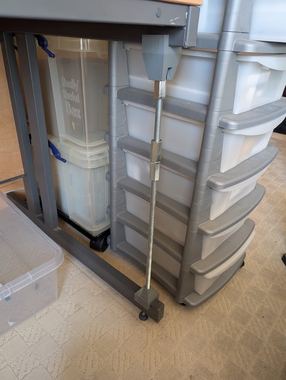
Yeah, my printer is on a worktop bench in my office, which was just using cantilever shelf brackets out from risers on the wall. I had to install an end bracket screwed to the wall and to the front edge of the bench top (the printer is on the end of the bench, up against the corner wall) and a vertical under the printer, screwed to a bracket in the floor. This is now a rigid setup, but it does transmit vibrations through the wall and floor. Fortunately we’re in a detached house, and the end wall with the screwed bracket is an outside wall, but still my wife complains of low frequency rumbles through the house when it’s printing. Not sure how to dampen them with such a heavy printer - my old Prusa was on printed spring feet, which effectively decoupled it from the room - this one is too heavy for that, I fear.
Just musing and decided it’s probably best to use a washer rather than the 5p, for a number of reasons. First it’s easier to slide back out 'cos of the hole in the middle (as long as the hole is still smaller than the diameter of the bar, so the washer still provides the running surface).
But also, 'tis a possibility that defacing Her Majesty’s Coinage…
…yes I know we have a King now, but it’s still ERII on all the 5p’s I have…
…may actually be an act of treason!
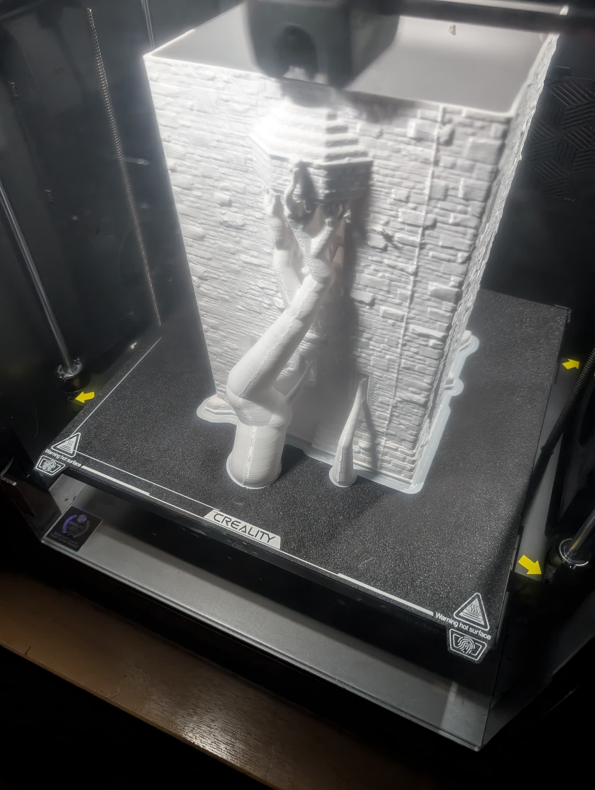
PS…I did manage to rescue the first print; not enough to use in place, but enough to prove proof of concept.
Now for the weeks of fine tuning and makin’ it look purdy…
Houston, I foresee a challenge but it probably does not matter. Euler buckling. That is a long column, unless you are using a 1 inch threaded rod. There is very little Z acceleration as the bed does not accelerate much compared to the movement of the hot end and Core X-Y gantry. I get no movement at the feet on mine but can feel some x-y movement at the top. I have been toying with the idea of securing the top of the printer to the wall as well via a horizontal plate/shelf. Removing two of the rubber top plugs, machining some aluminum custom standoff spacers for the upper frame bolts, longer bolts and It will get rid of movement and more importantly raise the resonant frequency of the printer as a whole and give me a shelf. More rigid, higher resonant frequency. Ghosting and ringing in the X and Y axes are the target of input shaping and from what little knowledge I have. In bygone days, printing a tuning tower quantified them at various accelerations and graphically represented any issues. I found this on ALL3DP https://all3dp.com/2/klipper-input-shaping-simply-explained.
All the sensors and macros on the K2 Plus seem to remove much of that old hassle.
Not sure how to set up to print a tuning tower on the K2…
On mine, Fluidd shows the following values:
## [input_shaper].
## shaper_type_x = ei
## shaper_freq_x = 42.8
## shaper_type_y = zv
#*# shaper_freq_y = 41.2
No idea if those are “good” or not thought.
The vertical rod is at 90 degrees to the X-Y issue and will damp those very little. After sleeping on it, plywood cheek plates against both legs for X and a plywood center plate from leg to leg for Y would make the desk more rigid but there would be some carpet shuffle. Plywood for two reasons, it damps vibration and is quite strong for its weight. Give the Z brace a go and see what transpires.
Sorry to hear of your pension woes. In the Great White North, being repeatedly poked in the eye by this lunacy, some of us saw the carnage coming. My brother and I did a Buffet (Warren) early and liquidated to cash equivalent.
I’m thinking self adhesive neoprene rubber of a decent thickness and resilience…too soft and the weight will compress it to a point where it’s doing nothing, too hard and well, it really WILL be doing nothing. I bought some to put under my A8, it was about 10mm thick, on a roll, but only about the same wide…I don’t know if it’s available in 40mm width? You’d need that for a pad under each foot.
Or…the sandwich approach…get a sheet of Kingspan (other brands of PU insulation are available, lol) and glue a sheet of ply to that. The layer of Kingspan should cut out a lot of noise transmission but it will need the ply to take the weight.
As to thickness…I dunno, how angry is your wife getting? It’s available from 25mm (won’t do much) over 150mm I think, but it’s got ridiculously expensive over the last few years. Double whammy I guess…energy costs went up, so it got more expensive to make, but everyone was installing it to save energy, so it became worth the extra cash.
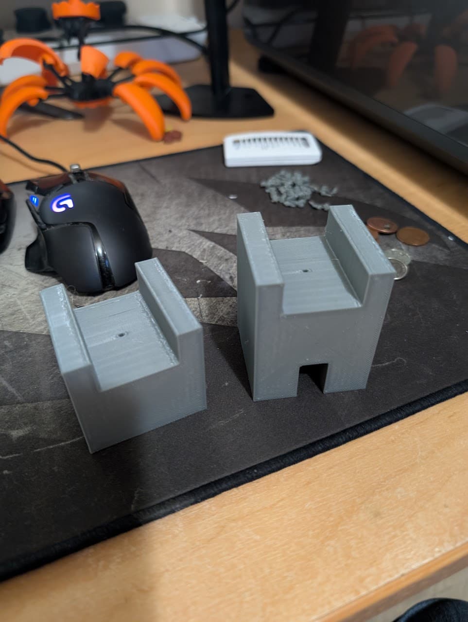
My first print was a bust…multiple errors on my part - silly things like not enough tolerance and printing solid.
Yes, solid. I might not have an anti-vibration solution, but if I put these two blocks in a sock, I have a pretty fine anti-burglar solution…!
Yeah my pension is supposedly “managed”. I was expecting better, but it’s too late now…just gotta enjoy the ride…

I considered that which is why I went from. M10 to M12…but in my case because of the cantilevered desk I have, most of the energy of the printer is being translated into movement as a sort of pivot around the X axis (in this case defining the X axis as running left to right (if sitting facing the desk as usual) and at the junction of the the cantilever’s upright with the bottom support rail.
I know this because the main cause of actual movement is when the printer does a lot of fast movement in the Y direction (from door of printer to litter tray), and very little when moving in the X direction (from filament cutter stop to spool holder). it is this movement I want to address as apart from the possible effect on print quality it makes my monitor dance which is quite disturbing.
Well., it’s in place and the desk is certainly “stiffer” in terms of resistance to hand movement. I’m going to re-run input shaping and then print the second pair.

Though…if I was looking for quality improvement I may have wasted two days of my time if this is anything to go by…!

A thought; the Creality guidance is to run input shaping with “no filament loaded”.
What does it mean by this? No filament in the CFS? Because I’m thinking sticking somewhere between 0 and 4 kg on top of the machine may have an effect…
Well, this seems to work exceptionally well. The vibration is still there, but the amplitude and energy of it seems greatly reduced; My monitor isn’t dancing around and it even seems quieter.
Not much point posting an “after” since I never posted a “before”. It will be interesting to see how much the second brace on the other side of t1he desk improves things.
Did see a YouTube video (by Thomas Sanlanderer IIRC) where he tested various thicknesses of foam and other materials. IIRC he got the best results with a little foam, and a large concrete pad under the printer. That was awhile ago, before these massive printers though.
Haven’t seen the video, but I’m not lugging a concrete block up my narrow stairs, and I feel putting it on a wooden floor would be sub-optimal anyway!
My braces are both in now and seem to be working well. I might share the design as this is a common type of desk in the UK. Even if people don’t have exactly the same one it may Inspire them!
Think it best to actually print something with them both on first though, so just waiting to dry some clear PETG for another interesting little diversionary project…
Yup and I think I’ve found out why @Cannonman was more concerned about X movement parallel with the door when a sort of rotational movement around the X axis is more what happens in practice. It’s hard to see in the photo but there’s an eighteen inch deep wooden stiffener in two metal channels that between the rear uprights. I think it’s often referred to as a “modesty” panel , as it stops lecherous old men looking at the legs of pretty secretaries.
1950s stereotypes duly noted, but still we make desks with modesty panels. Stereotypes may be wrong, but they are not always wrong…if you know what I mean…
Saved by lecherous old men. I did not see that panel before hence my concern but now I look with better eyes, I think I see it and it would control the parallel to door movement. Make sure whatever is attaching that modesty panel to the desk steel is secure because it is doing a fair bit more work than it was originally designed for I think. Your brace is taking care of the bendy bendy bouncy bouncy of the cantilevered load. Only remaining might be a bit of fore and aft (90 degrees to closed door) that cheek plates on the leg sides would reduce but by how much more I am not sure. This would be doing exactly what the modesty panel is doing but at 90 degrees to it. The double leg should be pretty stiff and prevent too much parallelogramming of the legs/brace in the fore and aft direction.
Glad to hear it is behaving better!
It’s welded into the channel frame as well as screwed in several places. There may be a touch of epoxy involved too. As all engineers know, movement causes wear…but I think it’s as restrained as it’s going to get, short of the addition of a few cubic metres of concrete, which I fear would just shift the target of my concerns from the desk to my old timber floor!