New to Forum and K2+ but not to multi axis NC manufacturing equipment. Ordered a K2+ a few weeks ago to possibly supplement/replace some processes/parts currently being produced. Requires filaments that have high temperature and stiff/brittle properties. K2+ claims for capability seemed plausible. However, we have been unsuccessful in using the K2+ for these processes using PPA-CF.
Apologize for the many image copies following, but Creality Forum has a character limit.
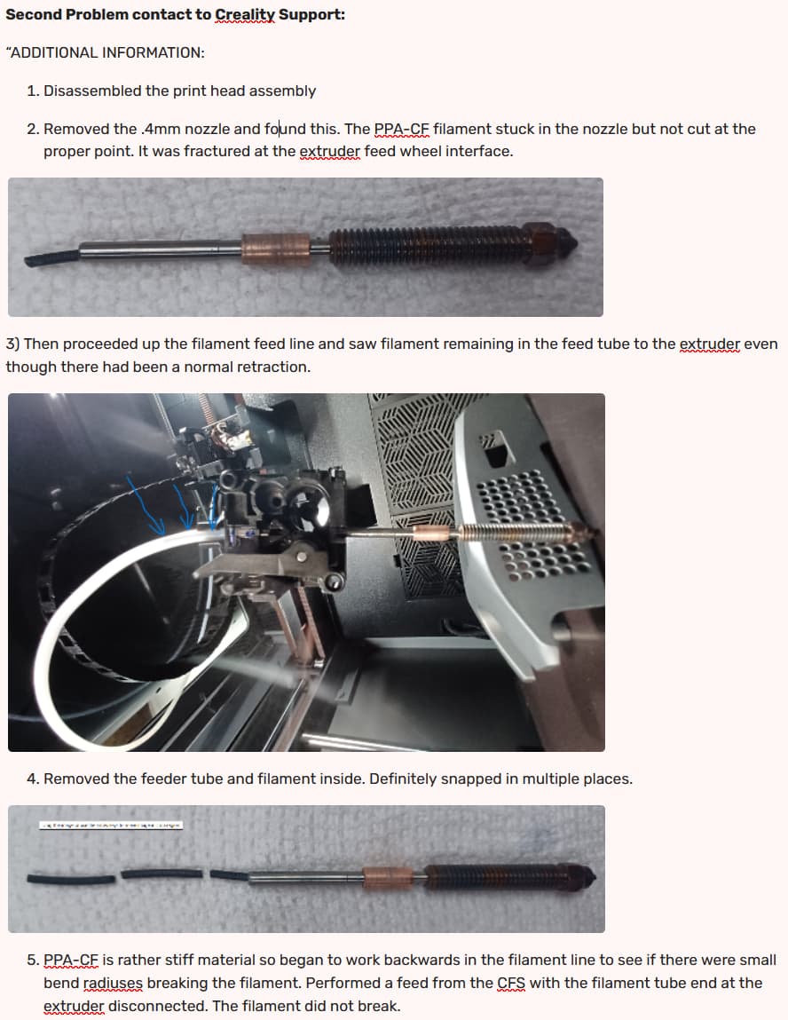
Ready to turn this over to the kids for toys in PLA and PETG!!!
Any ideas or protocols/settings with high temperature, enclosure required, stiff/brittle filaments are appreciated. I do not see much information on the forum concerning engineering material successful printing using the K2+. I am suspicious of component operation at high temperatures, or the basic stiff/brittle filament handling design being employed by Creality in the K2+ model.
Would welcome any user experiences that would help in formation of a consensus on Creality claims of use.
12/19/2025 UPDATE:
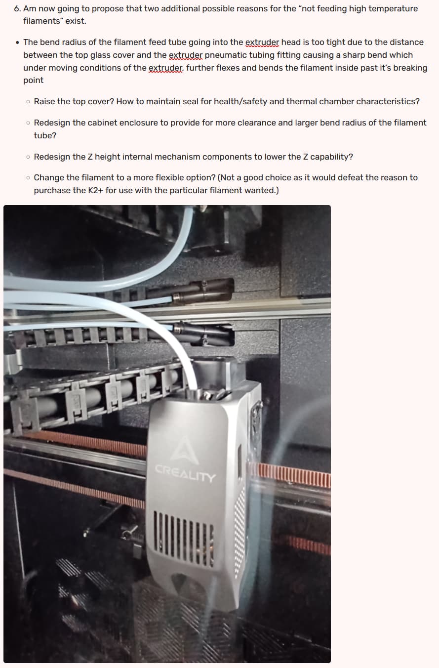
Verified extruder assembly Y axis movement under the front upper K2+ stucture rail snaps PPA_CF filament.
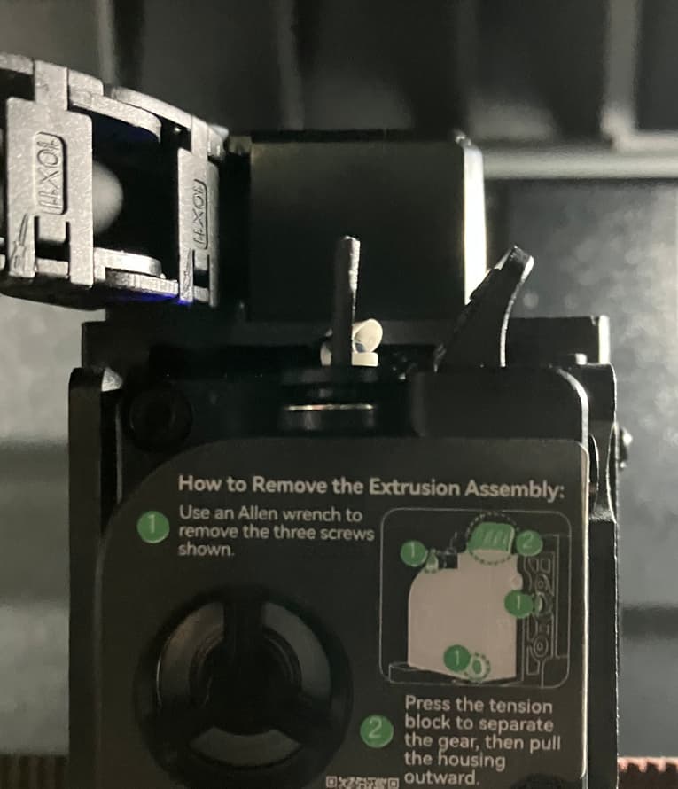
Before movement –

Moved extruder assembly to left forward calibration position – most generous bend radius, 2” riser, feed tube totally detached from cable chain, no Bowden tube support at the pneumatic fitting (max ht from pneumatic fitting to glass top for bend radius), 635mm feed tube length between extruder pneumatic fitting and cabinet hose penetration end, one counterclockwise revolution of feeder tube into extruder fitting (RH thread).
Heard snap of filament as extruder assembly/feeder tube proceeded to interfere with K2+ front upper structural rail –
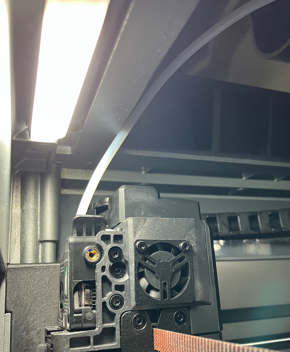
PPA-CF bend radius exceeded. (SNAP occured approximately 10mm from end of Y travel). Didn’t take much angle change.
So ……. project can be oriented to avoid the “zone of failure”, but how to prevent a calibration cycle (or operation) from entering this region of the Y axis? We machined some spacers for the Y axis guide rods (20 +/- 0.0127 mm), but without a root of the machine code, will not install the spacers out of caution to not disturb possible logic errors of the travel settings.
Considering redesigning/manufacturing a new upper front structure for the K2+. Back and sides do not have this issue because of the placement of the extruder filament intake point in the assembly. It appears Creality needs to address a “non-interference design” for their cabinet. Still have not verified this as the sole issue.
Any known way to limit the Y axis working envelope (change from 350 to 330 mm) (normal project parameters or calibration routines)? Then we can try the spacers instead of the cabinet redesign.