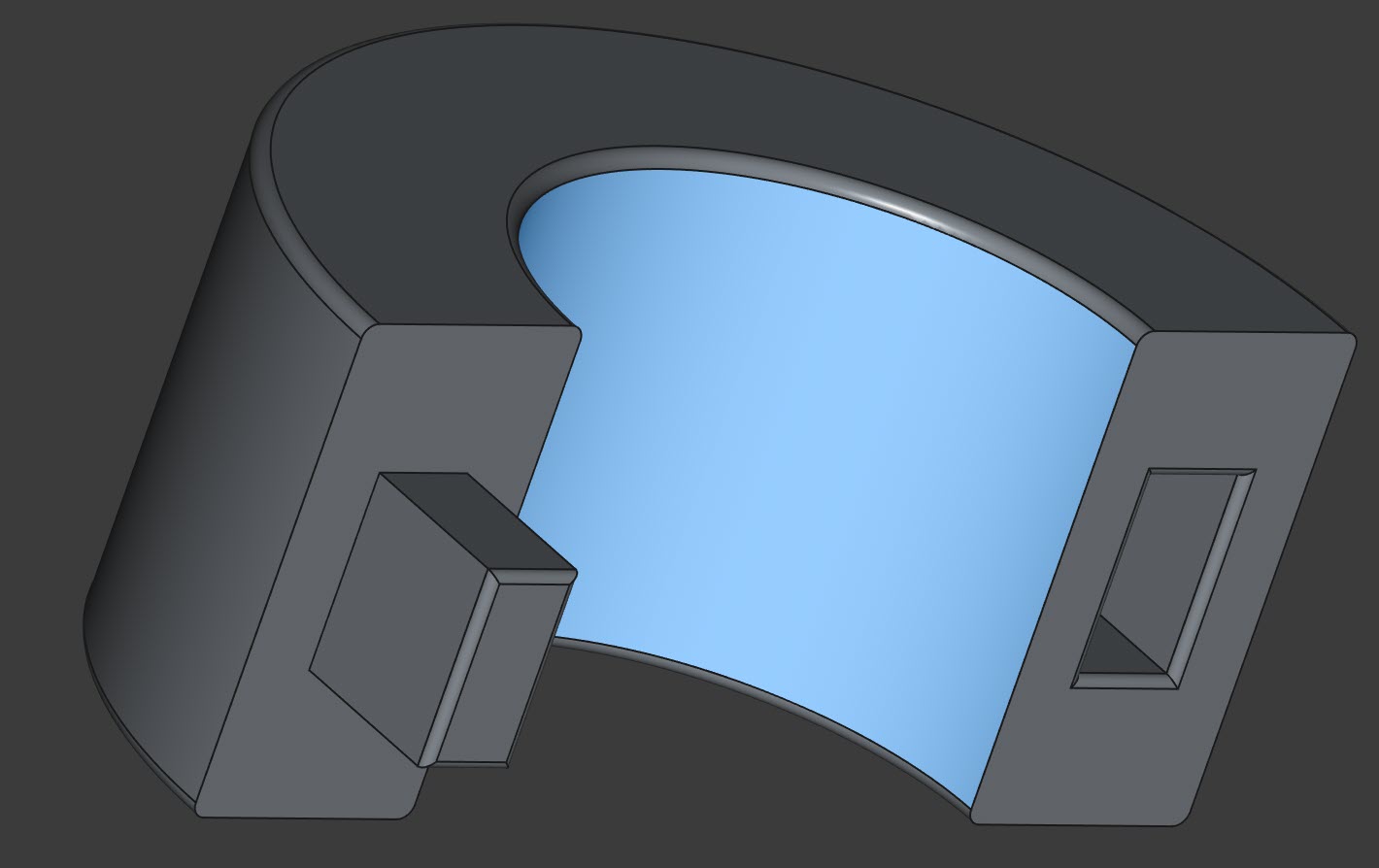
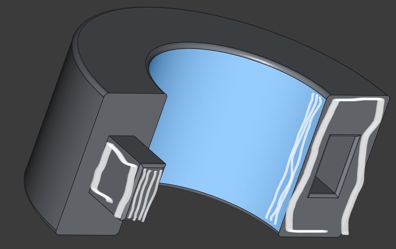
I have created a cylinder (actually looks like a long donut) using 2 halves. On the left side of each half is a rectangular protrusion and on the right side is a rectangular hole. The goal is to fit both sides together and by using friction, they will lock together around an existing shaft which I do not have access to the top or bottom.
I used FreeCAD to design the part using the following dimensions:
Body Dimensions:
Height: 10mm
Width: 5mm
Middle hole diameter: 12.70mm (this goes around the rod here:)
The problem is that the pad/protrusion would not fit into the holes and I had to minimally file the pads down and then it was OK. So for next time, how do I size the protrusions/pads and holes so that they “comfortably” fit together?
On all parts that need to fit into others, I decrease the ID by 0.14 for each side that interfaces with the other part OR increase the OD by the same. So, for a square hole 4x4x4mm, the interfacing square peg would be 3.72x3.72x3.86mm. For a circular hole 4x4, the cylinder peg would be 3.72x3.86mm.
Note that this is a tight fit on all my different printers. Depending on the layer line direction, pulling the parts back apart can rip the layers apart.
He is saying that if you want strength in the joined parts, you should print both pieces with holes and a joining pin with its layers in an opposing (right angle) direction.
Holes in both halves. In FreeCAD cut the pin off, mirror it in the cut plane and combine it. Then print the pins 90° degrees turned that the layers of the pin are vertical to the layers of the main part. Then push the two pins in the holes to connect the parts. In this way you don’t need to support the pins.