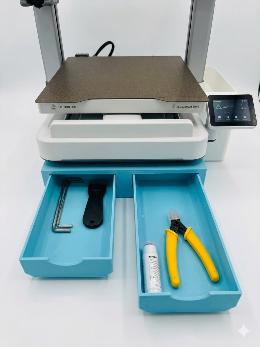
I recently designed and uploaded to Creality Cloud a base with drawers for my Creality Sparkx i7 3d printer. While I could have done the design in Autodesk’s Fusion or other free CAD program, I decided to design it using Creality Print version 7. Here is how i did it.
This was my process but I am not an engineer. Although I as a maker, I have started to learn Fusion and other free CAD programs, so this is probably very inefficient and if you see ways to improve this process I will not be offended.
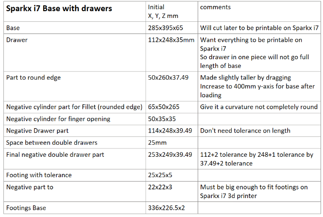
First of all we need to get all the measurements.
In hindsight I have all these measurement now but in reality I would keep going over to the printer and get measurements as I thought of them.
We will do the drawers first since we will need the drawer piece to build the base, you will see why when we do that part.
List of Steps for Drawer:
-
Create drawer base
-
Create part to use as negative to round bottom sides
-
Create negative part to be used round sides (make sure it doesn’t curve back on side or bottom or it will cut into the drawer where we don’t want)
-
Mesh boolean (right click doesn’t always work so use icon)
-
Save “curved edge” part to be loaded later as negative
-
Load curved edge as negative part and move in position on drawer base
-
Clone and Mirror curved edge (center? And move only on x or use move command to get same position)
-
Mesh boolean
-
Clone for drawer part later
-
Hollow
-
Cut top and resize to 37.49 high
-
Add cylinder to make finger opening for pulling drawer
-
Mesh boolean
-
Save final drawer as stl to add to final .3mf file
-
Take base with rounded edges and before hollowing
-
Add tolerances of 2mm (1mm for each side and top/bottom) and 1mm on y-axis
-
Clone and center and move on x only then meaure to be 25mm apart
-
Save as negative part
List of Steps for Base (ignore/close message about objects being too big for bed plate):
-
Create part for base (will initially be bigger than bed plate until cut)
-
Load negative part for curvature and increase to 400mm
-
Clone and mirror - move into position
-
Mesh boolean
-
Load negative double drawer part
-
Center then drag forward to just stick out
-
Mesh boolean
-
Create footing cylinder
-
Create negative part and move tops to be even leaving 2mm for opening
-
Mesh boolean for final footing
-
Print footing to see if it fits on printer foot (resize as needed)
-
Create base size of outside distances between feet (front to back and side to side)
-
Place footing at edges of footing base
-
Mesh boolean
-
Clone and cut length and width pieces for testing (adjust as needed)
-
Save adjusted base as stl (copy and paste to base and assemble)
-
Load footing base as part and move up to only footings are above base
-
Cut base with Mode Dovetail
-
Mode dovetail
-
To get dovetail right first move cut from flat to upright going to side (not front) then rotate
-
Move cut position to be up and down and slightly to back (because front piece will be hollow for drawers and back will be solid-to even print out times: not important)
-
Depth 25, tolerance .2mm
-
Width 20, tolerance .15mm
-
Flap 80 degrees
-
-
I moved this around manually using sliders so the cut would not be inside drawer space
-
Perform cut
-
Clone and cut top 4mm for print to test dovetail cut (can also test overall fit in total before final print)
-
Move pieces to two separate plates (4 total with 2 drawers)
-
Orient so no supports are needed
Save whole .3mf and delete unneeded parts and add drawers stl and save final .3mf for printing later.
Print and enjoy
I created a YouTube video of the entire process. It is kind of long at around 50 minutes but you can watch in 2X speed!!! See the link below.
Youtube.com link:
https://www.youtube.com/watch?v=xfNnKZ2gp7g&pp=ygUYbW9kZWxpbmcgY3JlYWxpdHkgc2xpY2Vy0gcJCcUKAYcqIYzv