The real reason of first layer issues, and a solution

A huge proportion of the complaints about the K2 Plus (and probably other CREALITY models as well) revolve around first‑layer difficulties. Most users have ended up resigning themselves to babysitting the first layer every single time, manually adjusting the Z‑offset as soon as things start going wrong. What’s most frustrating is the lack of repeatability, especially for those who—following CREALITY’s rather strange advice—recalculate the mesh before every print.

The following experiment will point you toward the real reason behind these issues, and how to fix them while waiting for CREALITY to update their software properly.

WARNING: Everything that follows assumes you have not patched the machine’s configuration files in any other way.

In the file printer.cfg, temporarily replace the line (in the bed_mesh section, around line 360):

  probe_count: 9,9

with
probe_count: 3,3

This will quickly generate a 9‑point (3×3) mesh. The goal is not to print with this mesh, but to observe what happens when the same algorithm is repeated.

In Fluidd, under the Console tab, run the following commands N times:

BED_MESH_CALIBRATE

and
BED_MESH_OUTPUT

You will collect N mesh matrices, each representing the measured height of the nine points. In a perfect world, the matrices would be identical, but no measuring instrument is perfect. The only real question is whether the observed deviations are acceptable given how the measurement is used.

I ran the experiment 10 times (you should try it—it’s quick since there are only nine points). Your results will differ from mine because every machine is different, but you will likely see the same pattern. Here’s what I observed on my machine:

  • The maximum deviation between the 10 measurements for any of the nine points was 0.068 mm, which is 34% of a 0.2 mm layer height.
  • The average absolute deviation across the 10 measurements was 0.032 mm, or 16% of a 0.2 mm layer.

With a supposedly constant flow—which already puts the extruder under pressure to compensate for pressure variations—it’s easy to see how this leads to ripples and lifting that ruin the first layer. The measurement error at each point of the bed is simply too large to produce a reliable first layer.

WHAT TO DO

First, a few thoughts that go against common assumptions:

  • The main quality we expect from a mesh is not how flat it is (though that doesn’t hurt), but how accurately it reflects the actual topology of the bed.
  • The topology of the bed has no reason to change from one print to the next (otherwise it could also change during a print).
  • It does not change when you update the firmware, switch filament types (PLA, PETG, TPU…), install a new nozzle, a new hotend, or even a new extruder—even a non‑CREALITY one.
  • As long as you don’t touch the gantry or the bed itself, the topology stays the same.

With a bit of luck, you might get a mesh whose error is small enough to give you “good enough” prints. If you ever manage to obtain such a mesh, keep it, because the odds of recalculating a better one are low.

The real question is whether we can force that luck and obtain an acceptable mesh. When a measuring instrument produces unacceptably noisy data, the scientific approach is to repeat the measurement N times and average the results, reducing the error by a factor of 1 / sqrt(N).

CREALITY knows this perfectly well: the reference Z measurement at the start of each print is repeated several times (at least 5), with additional checks likely used to discard outliers.

So, in theory, CREALITY would only need to measure each mesh point N times to produce an acceptable mesh. And indeed, machines equipped with a prtouch probe have a samples parameter in the [prtouch_v3] section of printer.cfg. Unfortunately, on the K2 Plus, changing this parameter has no effect on the mesh calculation.

Thus, the mesh problem would be solved if CREALITY simply enabled this parameter, allowing users to choose between a fast “bad” mesh and a slower “good” one.

In the meantime…

You can approximate this behavior by performing several mesh measurements, averaging the resulting matrices, and replacing the mesh stored in the commented section at the end of printer.cfg.

However, there is a crucial detail: Each mesh is measured relative to a Z reference that changes slightly from pass to pass due to measurement noise. You must not average the raw matrices. You must first normalize each matrix by subtracting its own average value.
The algorithm is:

  1. Choose a grid size N (9×9, 11×11…). The “right” value is another topic I’ll return to later.
  2. Run BED_MESH_CALIBRATE then BED_MESH_OUTPUT P times, saving each matrix.
  3. Normalize each matrix by subtracting its mean value.
  4. Compute the average of the P normalized matrices and paste the result into the mesh section at the end of printer.cfg. This averaged matrix becomes the default mesh at the next reboot. Be extremely careful with syntax—this part of the file is not meant to be edited.

To ensure the mesh is always loaded after reboot, add the following line to the [gcode_macro START_PRINT] macro in gcode_macro.cfg, after:

 NEXT_HOMEZ_NACCU
 G28 Z

add

 BED_MESH_PROFILE LOAD=default

Reboot the machine, then adjust your Z‑offset, which should now be close to 0 and depend only on the filament.

MY RESULTS

After validating the method with a 13×13 grid measured 10 times, the resulting mesh produced an almost perfect first layer up to a 250×250 mm square. Minor defects appear beyond that, more visible as the print size increases. This is due to a fundamental limitation of interpolation algorithms: they cannot interpolate accurately near the edges, and even less near the corners.

With a 13×13 matrix, the outer 25 mm border is poorly reproduced. The closer you get to the edge, the worse the approximation. To print larger areas, you must increase the matrix size, but measurement time grows with the square of the grid size.

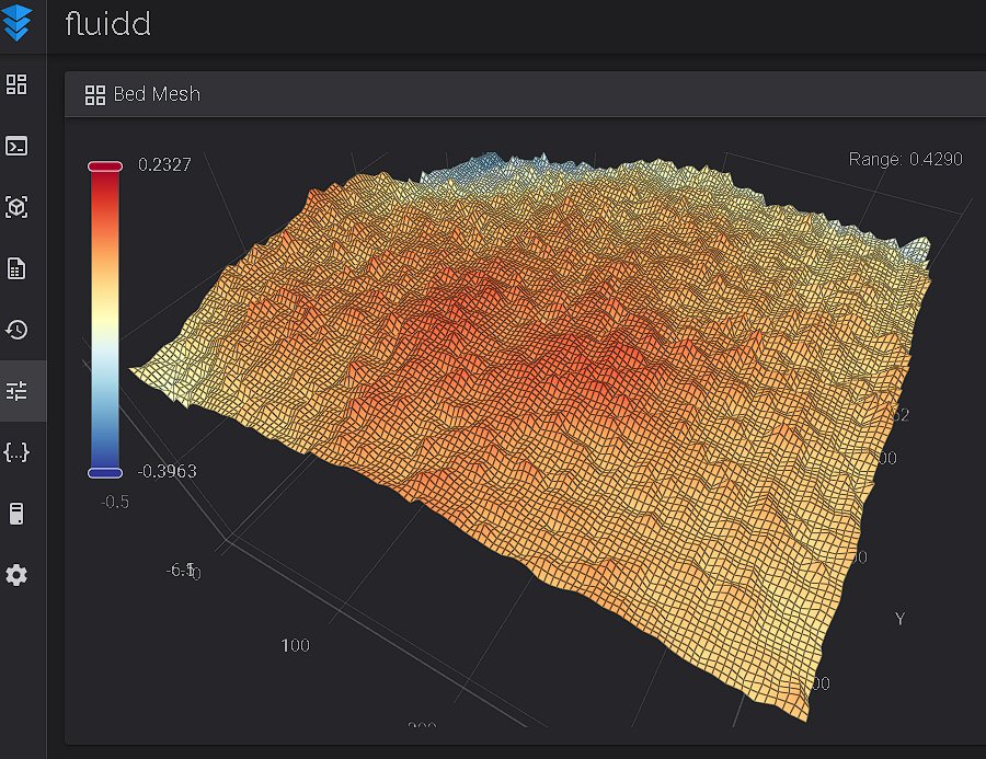
Being a compulsive perfectionist, I pushed things far beyond reason. With a 65×65 matrix (4225 points) measured 17 times (two full days of measurements), here is the resulting mesh (range 0.4290 mm—not impressive on paper):
But in practice, it allows me to print a 348×348 mm first layer (leaving room for a skirt) with perfect repeatability, as shown here:
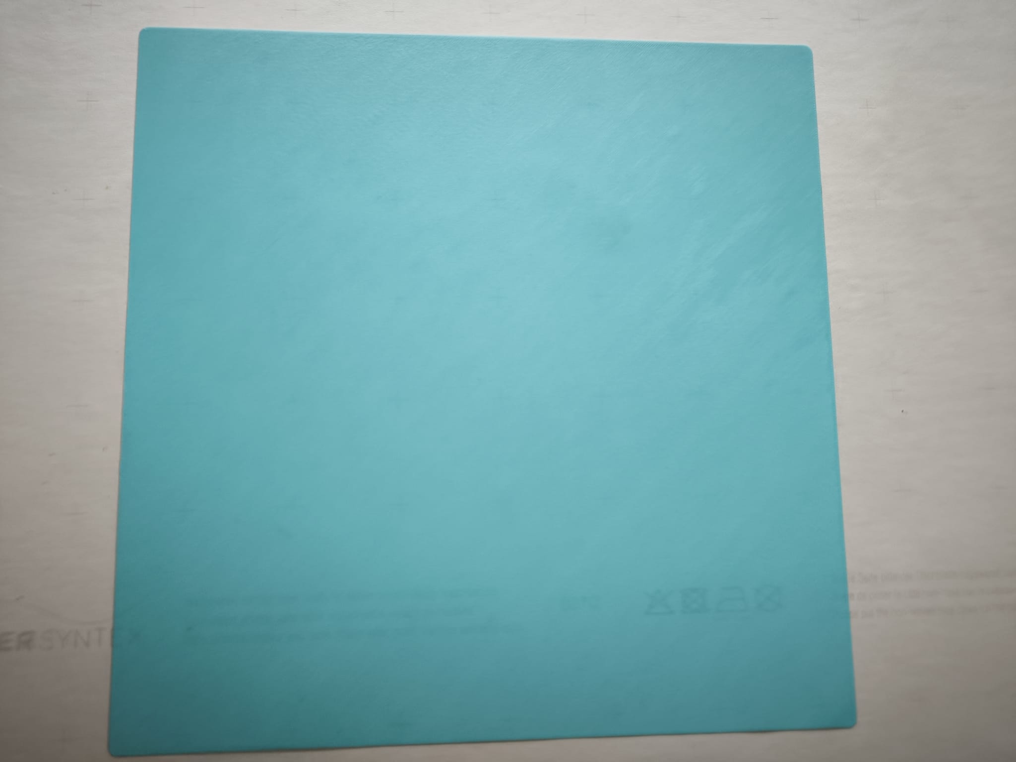
I’ve been using this mesh for two weeks. I’ve printed large PLA parts and smaller TPU parts. I will never repeat this experiment—it produces a level of perfection no one actually needs—but this will remain my reference mesh until I’m forced to modify the bed. (As a precaution, I never touch the magnetic build plate.)

This experiment makes one thing unmistakably clear: the machine itself is not the problem. The K2 Plus delivers excellent flow control, applies mesh compensation reliably, and is mechanically solid. The only real flaw is a software decision — CREALITY’s choice to prioritize mesh‑calculation speed over mesh quality. That trade‑off cripples first‑layer consistency, and users shouldn’t be forced to live with it. CREALITY should simply give us control: a parameter that lets the user decide how many times each probe point is measured. One small change, and the entire first‑layer experience transforms.

A French version of this post is available on this forum.

LAST NEWS: The above mesh has been used countless times with PLA TPU & PETG without any change in output quality. To prepare for a possible future hardware change, I performed a second experiment with a 17x17 matrix averaged 5 times. The result is nearly as good as the previous one. Some smaller figures will likely give, at a lower cost, sufficient quality for building on top of the first layer.

10 Likes

@CREALITY Can we fix this with the next firmware update? I cant start a print without being at my machine to adjust the Z Offset, it makes the rest of your ecosystem useless.

2 Likes

I too have often wondered whether the real problem was the low number of probed points and the accuracy of them. You’ve done an excellent job here, and are to be congratulated. Thanks for your efforts for the benefit of us all. I for one would be happy to have a high-resolution bed mesh selectable in the standard UI.

Again, THANK YOU!

3 Likes

Hi, I just sent a short technical report to Creality technical team for that.

3 Likes

Thank God for OCD people.

I am one but getting too old to care enough in many places now. I have to conserve my mental health more than when I was younger and full of piss and vinegar.

I take my hat off to you sir.

BTW…I have never adjusted my z offsett in a year on my K2 Pro. On my ender 3 I adjusted occassionally but adter a heat plate cord break I levelled the heat bed using wrenches to bend the plate flat so the tension springs actually worked. What an improvement without curves in the bed.

2 Likes

Same here man. My k2 Pro is literally hit print and walk away. My k2 plus on the other hand I have to baby through calibration (IN PERSON min you) and adjust the Z Offset manually in klipper. Meaning I don’t have the ability to print from the creality cloud app because the first layer will also just be bad.

I saw a video yesterday that if you know your z offset off by a certain amount almost every time, you can add a custom macro in fluidd so the firmware will take whatever z value is applied by print precalibration and add your adjustment.

Seems like a lot of work that will eventually be off again, with the added possibility of possibly bricking your firmware from altering the firmware code.

Doing the lords work :folded_hands:

I will definitely be giving this a try. This is the single biggest pain about the K2 plus. Something so simple shouldn’t be this hard.

1 Like

Somebody (Ronald Bailey) has written a macro that automates the whole process. He told me he will publish it.

1 Like

Thank you for a very hard boiled complete statistical analysis of the machine. OCD? Perhaps, but you can also backup your observations given generally accepted statistical techniques. My only question would be to ask, what about temperature effects on the results going from a cold bed to one running at 70° to 80°? I don’t think that a complete run of your oversampled system would be necessary. Perhaps just sampling of the extreme points from your complete run.

Thanks!

1 Like

Thank you :melting_face:Until now, I have only used this mesh with PLA, TPU, and PETG with no significant difference. Not for extreme temperatures. If, in the future, I have to go to much higher temperatures, I think I would make a different mesh if proved necessary.

I think the consensus is that the bed warps significantly at higher temps. And preheat it for 30min before doing any leveling. Of course there are all kinds of after-market mods such as graphite beds. But the whole reason we bought a “flagship” was to get away from the unwritten upgrade requirements of the original Ender-3…

  • PETG has been so unreliable on this K2+, I don’t even attempt it anymore; printer just sits and collects dust. Ironically, ABS seems to print much better.
  • Have a bullet-point list of notes for attempting PETG, including manually adjusting Z offset each print. Showed this list to a co-worker whom owns a different (real) flagship printer, and they won’t touch this thing. They’ve asked repeatedly for me to print a large PETG model, and repeatedly I’ve showed them the list. I’m not going to attempt it - waste of time.

Hi Mark, whether the bed warps at higher temps is not within the scope of my post. Personally, I do not print at very high temps because I use only TPU, PLA, and PETG. However, I did not see significant differences between TPU (45°C) and PETG (70°C) in this regard. With a stabilised temperature, I always had more differences between two meshes of the same filament than between TPU and PETG … This gives me the idea to try, when I have some time, to quantify this issue with systematic measurements.

About PETG (I use SUNLU PETG) , once the right parameters are found, and K2 plus Generic PETG is a very good starting point, I do not encounter more problems than PLA, except that I try to avoid, by design, acute angles on thick objects.

Sorry to as such stupid question…

I used a 3D printer out of the box about 13 years ago, without worrying about tweaking (if it was ever available) the old software. It stopped working about 2 years ago and thought about replacing it as I might need to do some 3D printing for jigs in my woodworking workshop, and finished up impulsively buying a Creality without any due diligence.

I have had my Creality K2 Plus for about 3 months now and it’s because of these types of issues I’ve read that I’m too afraid to start it up… is this an issue that a 77 year old noob needs to come to grips with right from the start or is it for the experts that need perfection.

Hi Alex, If I had to be afraid because 77 years old, I would have stopped 3D printig 5 years ago :wink:

I love your assessment.

A few tips on meshing.
make sure your zero reference point is set to your main home z probe location. If this is bed center (like most), be sure that you use a probe count that keeps this spot “probe-able”.
Usually an odd number divisible by the probe area. I choose 17x17 probe points, in a 300x300mm area; from 25 to 325 in both axis. (I have a 360x370 bed, but use a 355x355 cryogrip flexplate)
I probe 5 times each point. (using Bi-Cubic on the mesh, and Median in bltouch config;) effectivly result in the math throwing out the high and the low values of the 5 probes, and then averaging the remaining 3.
This gets around Klipper’s “outlier first probe after a horizontal move” (continuing issue) and gets me a more precise measurement from each location. I use touch mode with the bltouch (doesnt retract pin between probes) which saves “alot” of time.
I dont usually run a full mesh now that print_area meshing is in mainline klipper. but when I do, its this technique.

So thank you for your writeup, I feel you bring up a great point.

edit: Its all in the math, and you have to calculate based on your printers mesh area.
```Q: In a 15x15 grid, (16 x16 points) will there be a center point in both axis
A: No, a 15x15 grid (16x16 points) will not have a single center point on either axis.
Because 16 is an even number, the points are split evenly into two halves of 8. The exact middle of your grid will fall in the dead space between the 8th and 9th probe points.

Why the math matters
Odd number of points (e.g., 3, 5, 7, 15)
Has a true center point. and will match your Z home position.
Even number of points (e.g., 4, 8, 12, 16)
No true center point (the center is a line/gap).
Grid options with a true center point
If your application requires a probe point exactly in the physical center of a 150mm x 150mm bed, you must choose a grid layout that results in an odd number of points along the axes.
Here are the best alternatives from your original 150mm layout options:
10x10 Grid (15mm squares)
11 x 11 points. The 6th point on each axis is the exact center.
6x6 Grid (25mm squares)
7 x 7 points. The 4th point on each axis is the exact center.
2x2 Grid (75mm squares)
3 x 3 points. The 2nd point on each axis is the exact center.```

Hope this helps understand my point above regarding number of points.

1 Like

Many thanks for your contribution. I particularly appreciate your choice of “median” vs “average”. This is a good choice for a small number of measures. My question is: how do you manage to probe each point given that Creality K2 plus software ignores the parameter “measures”?

Has it been published? I looked but didn’t see it.

Hi Charlie, you are on the publication page.

Thanks! Its definitely not my machine. Physically its fine. I replaced the stain gage, toolhead cable, and the toolhead board and complete nozzle and hotend over the past 2 weeks, and my bed mesh is reading -.01 to -.06 depending on where on my bed it is.