Well children, are you sitting comfortably? Then I’ll begin.
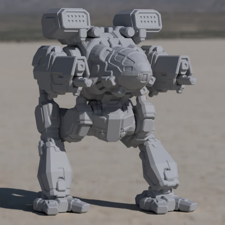
My desire to print large but detailed Mechwarriors on my 3D printer wasn’t the reason I bought one, but it became something of an obsession. Seeing models like this one just served to fuel it;
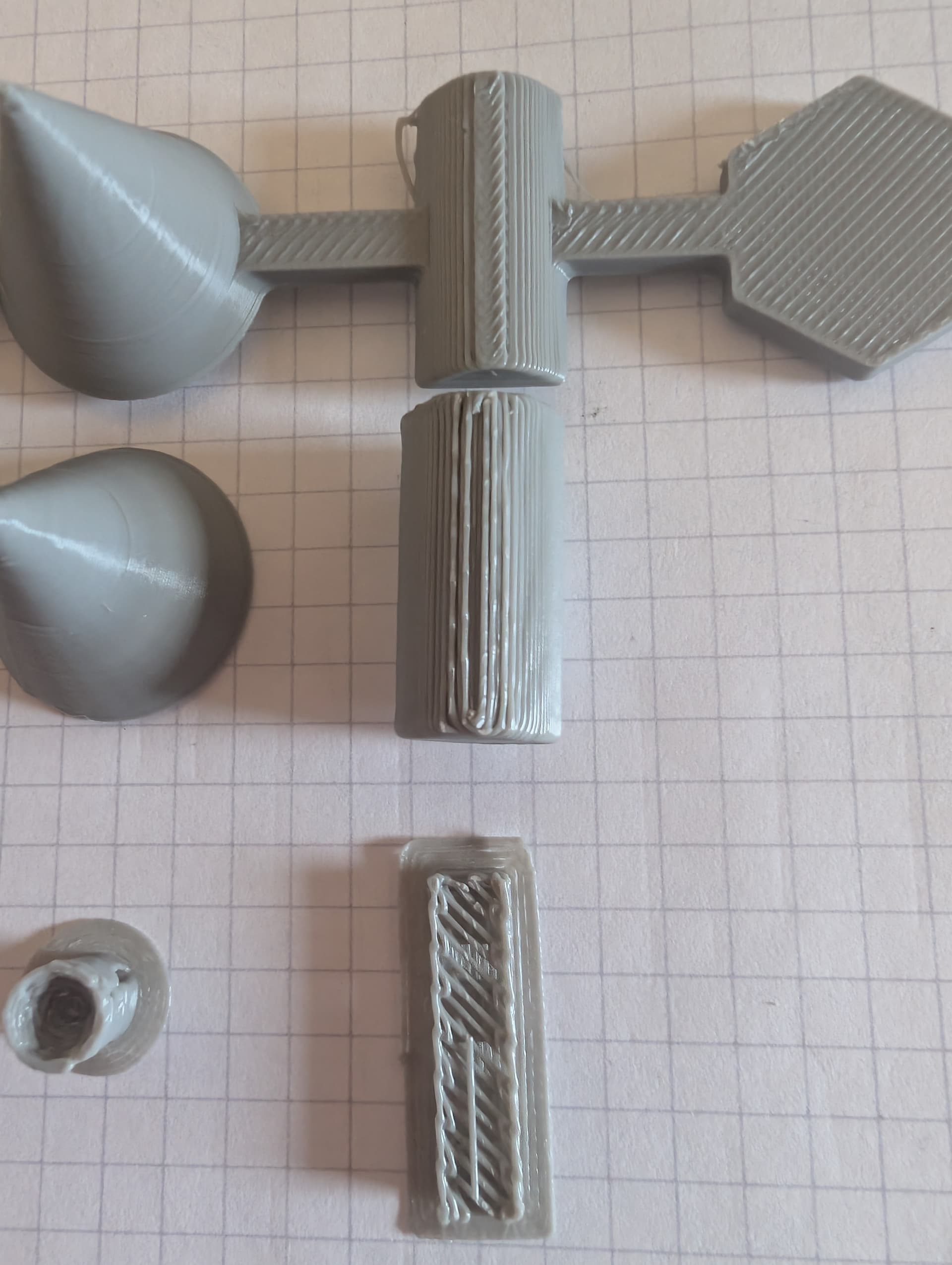
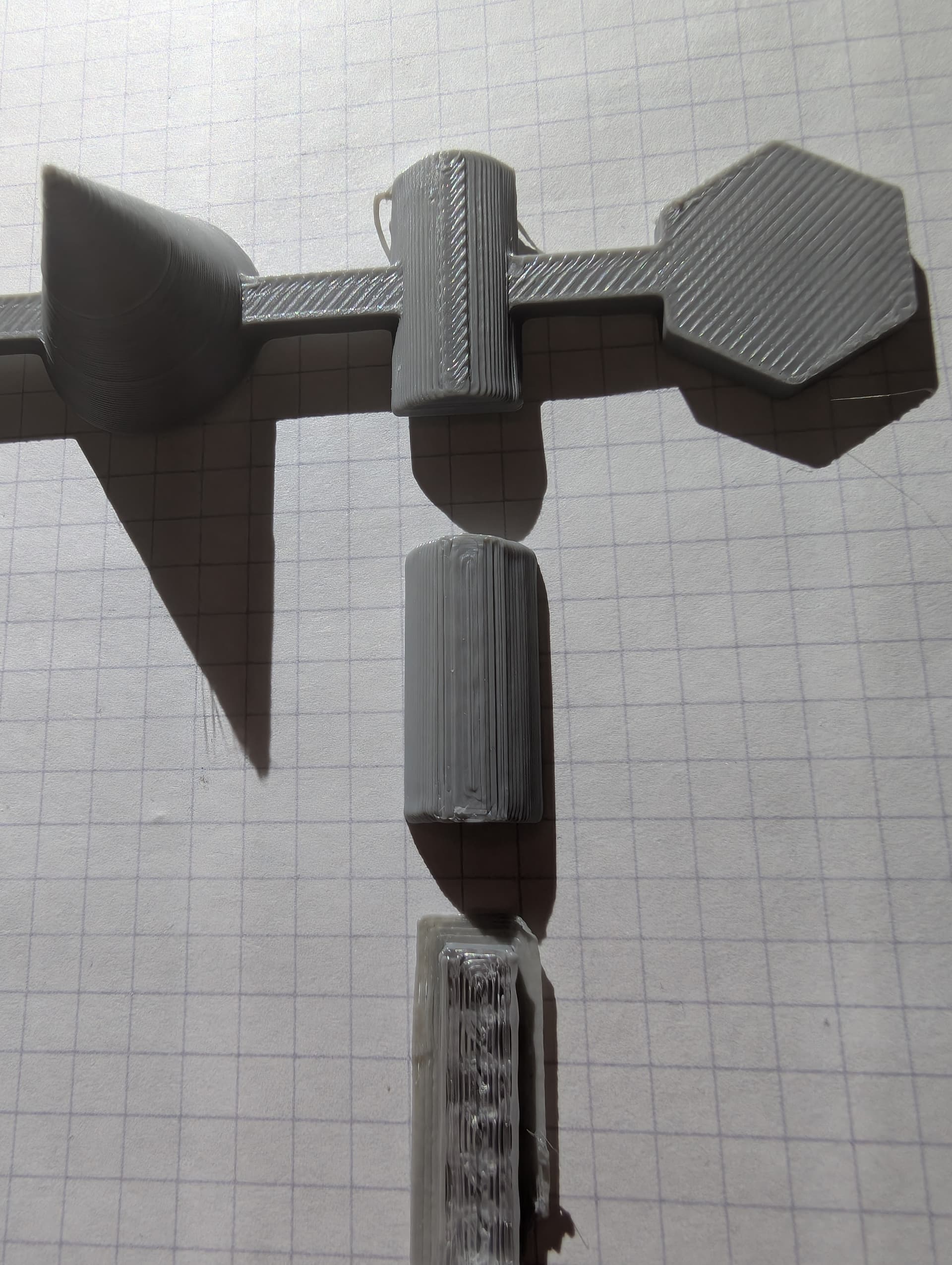
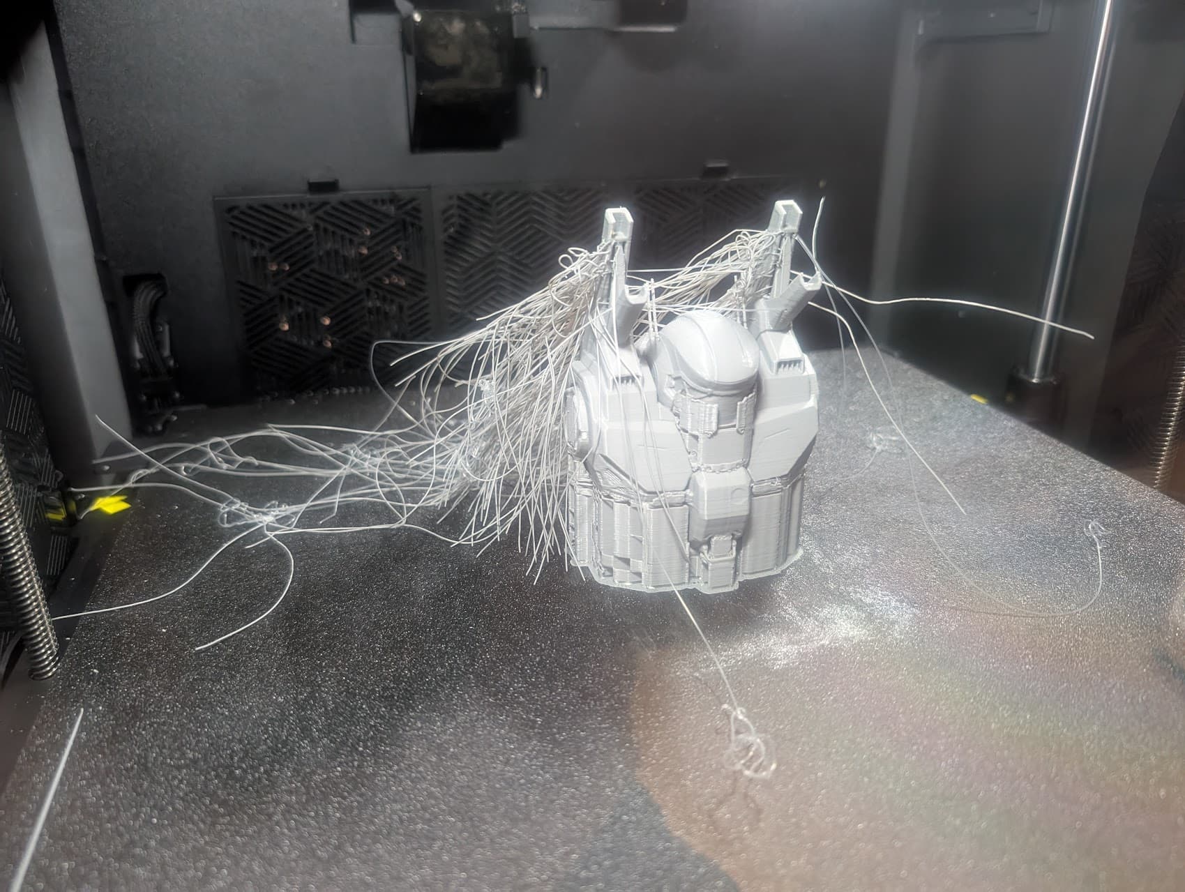
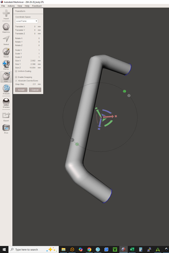
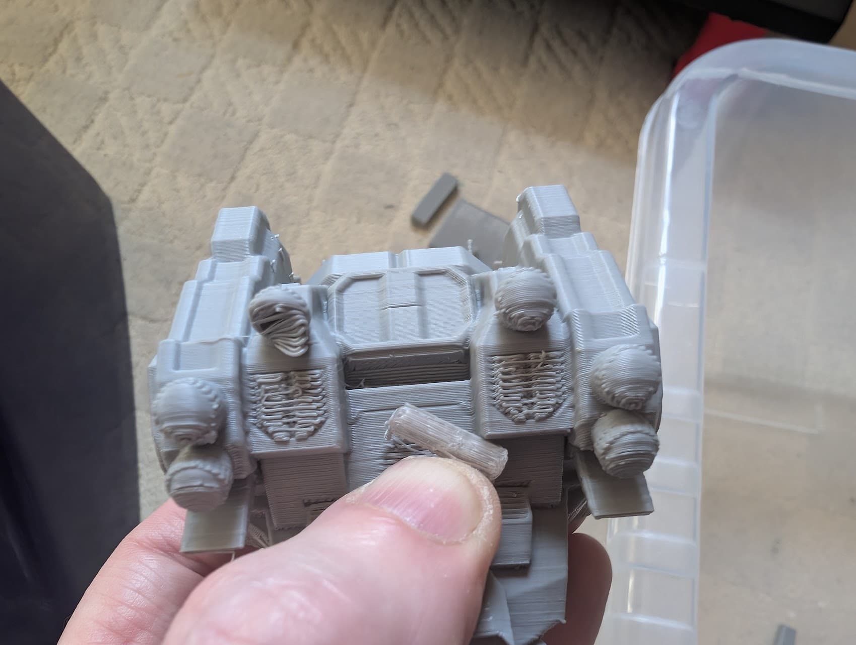
But, it’s not easy. The models are very much designed with resin printing in mind, and even then the level of detail required is challenging to say the least - consider this part on the model I’ve been trying to print overnight;
The whole part is 2mmx2mmx10mm - meaning the diameter of the handle is 0.83mm. Beyond the challenges of actually printing it on a 0.4mm nozzle, it actually “floats” as it’s attached to the underside of the mech, and thus requires support from below.
It’s impossible. Or is it?
The improvements to the cylinder in the OP made me think it might not be,
The idea was that the quality was so poor because in supported areas the nozzle wasn’t working on a solid surface. You can’t make the support 100% solid and intimately close to the model because then it’s not support any more; it’s part of the model and you’ll never get it off.
So - support material. Something that will form a good enough surface, but not stick. There are a few of them, including water soluble ones that have the advantage of requiring no force to remove. But I decided to try the “Support for PLA/PETG” by Bambu.
The problems are evident before the advantages, so I’m going to list them first. There’s basically three; time , cost and effort.
Time is a big one. the body of the Mech I chose would print (if it were possible) without support in 2h 15m. Setting the support to use the separate material bumped that up to 12h 29m. Add in that there’s still time required in removing the support and some other post processing however minor and that’s a big consideration.
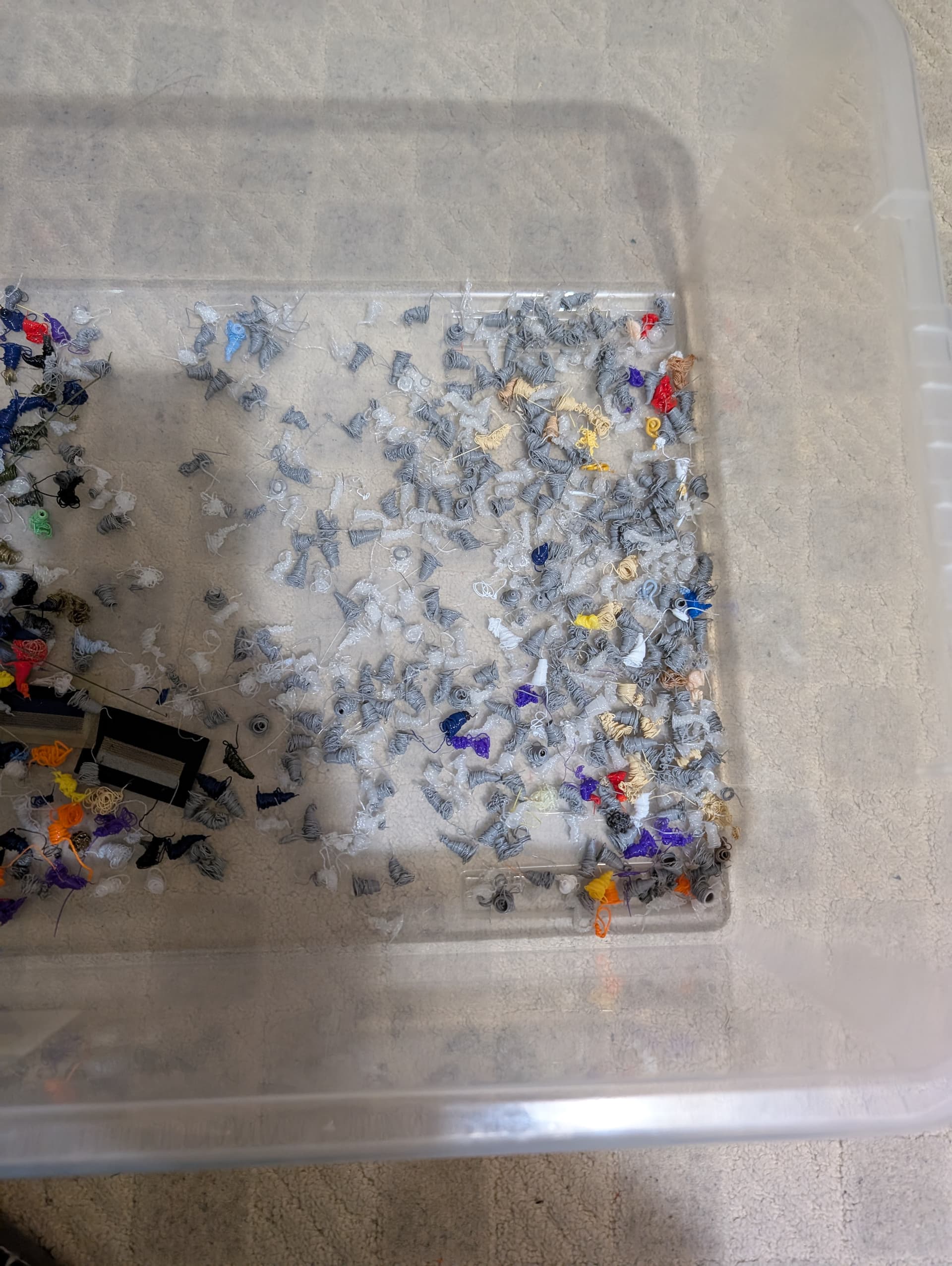
Cost. I may have set the system to only use a 5-layer section of interface from the support filament, but the constant visits to the litter box on every filament change mean this model (which just about fits in the palm of my hand) used a good half a roll of the support filament. That’s £15 - and this is just the body of the Mech. Bye bye, profitability.
Effort. On this model, removing the support was a dream in some places, a nightmare in others. There were parts that literally came away with the slightest touch leaving behind a nigh-perfect surface. but there were also parts where the support was effectively trapped in voids that were larger than the entrances to them. There were also parts that failed because the support came away TOO easily during the print.
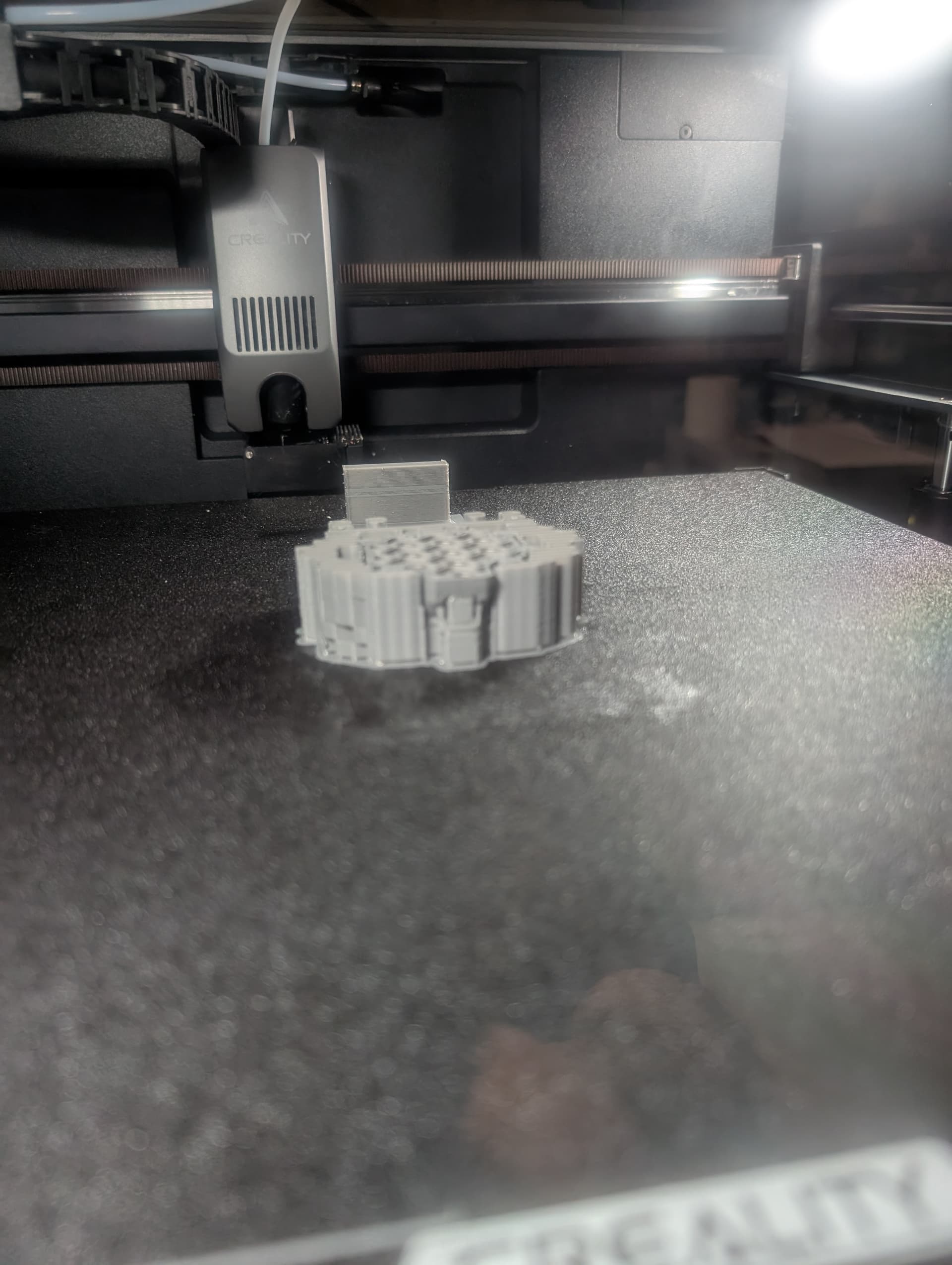
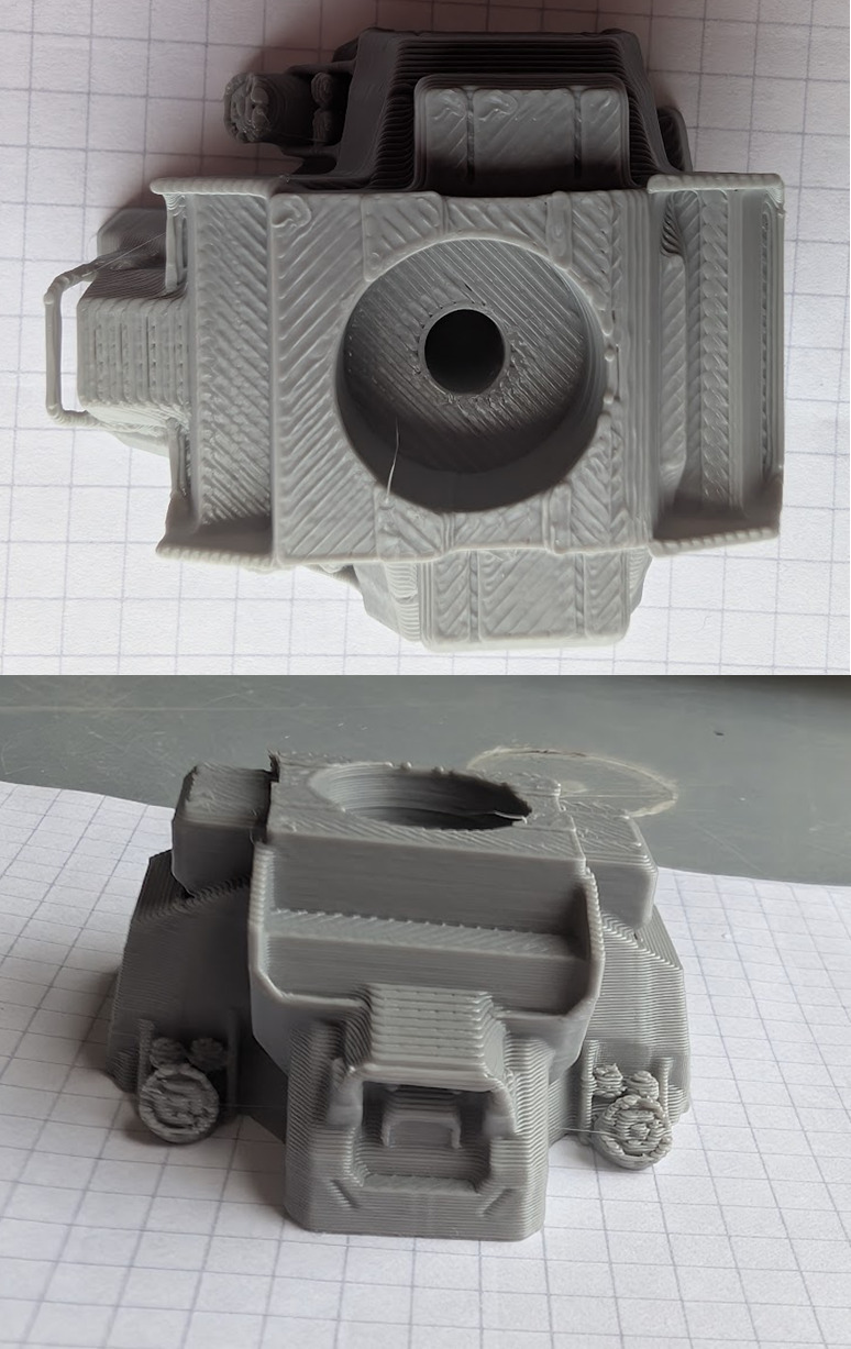
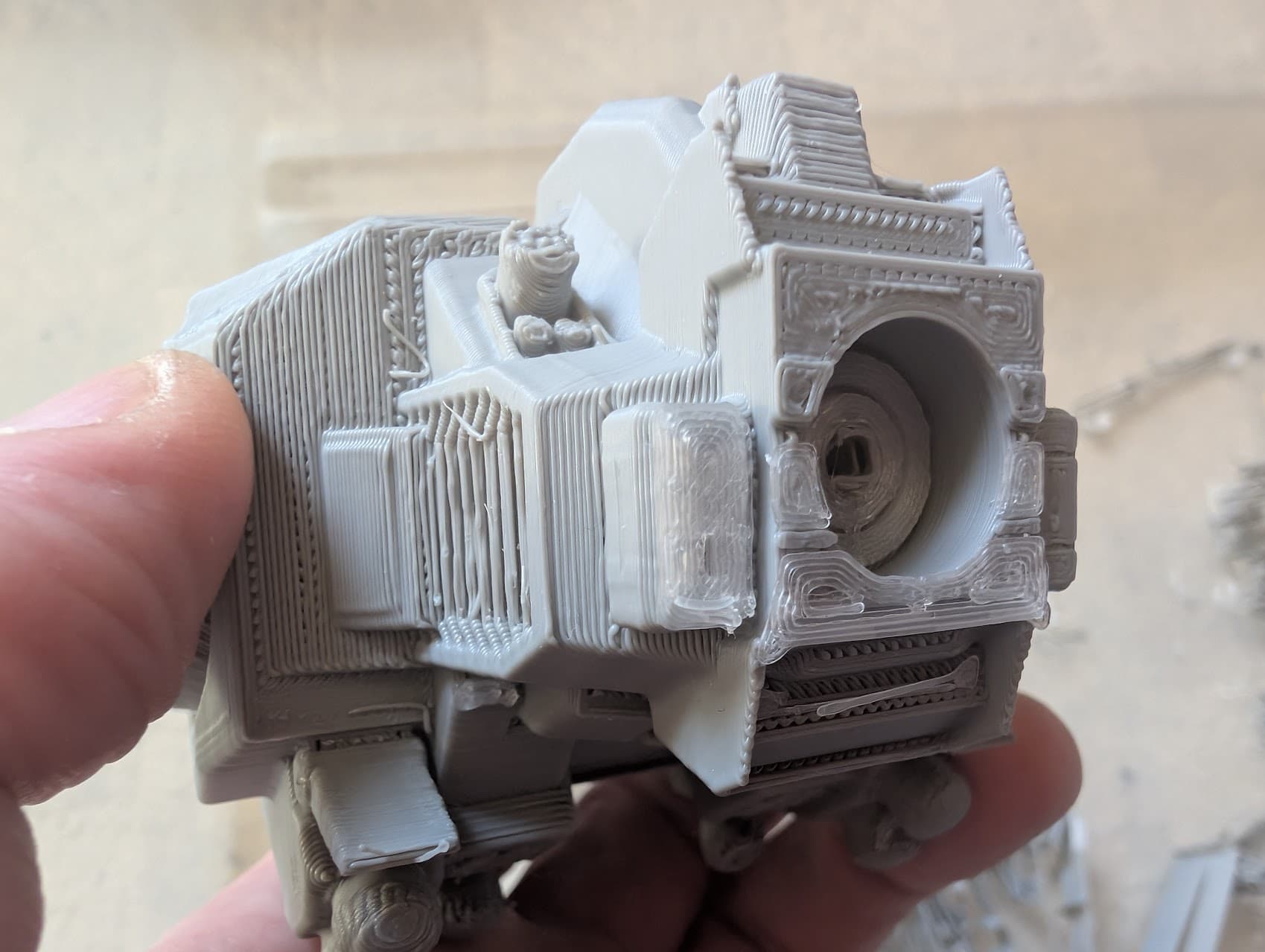
Right…on to the good stuff. Remember that last 15-minute print? Here it is;
It’s just the bottom of the Mech, sliced off and turned upside down, printed without supports. This is my target. Note it includes the handle detail (far left of the top pic) and reveals that there is detail in the exhaust ports, which I hadn’t even noticed before.
A nod here to the K2+. I can’t overstate how impressed I am with it’s ability to print a 0.83mm diameter handle over a 10mm distance with a 0.4mm nozzle. The room for error must be precisely zero. Round of applause for the Creality team please!
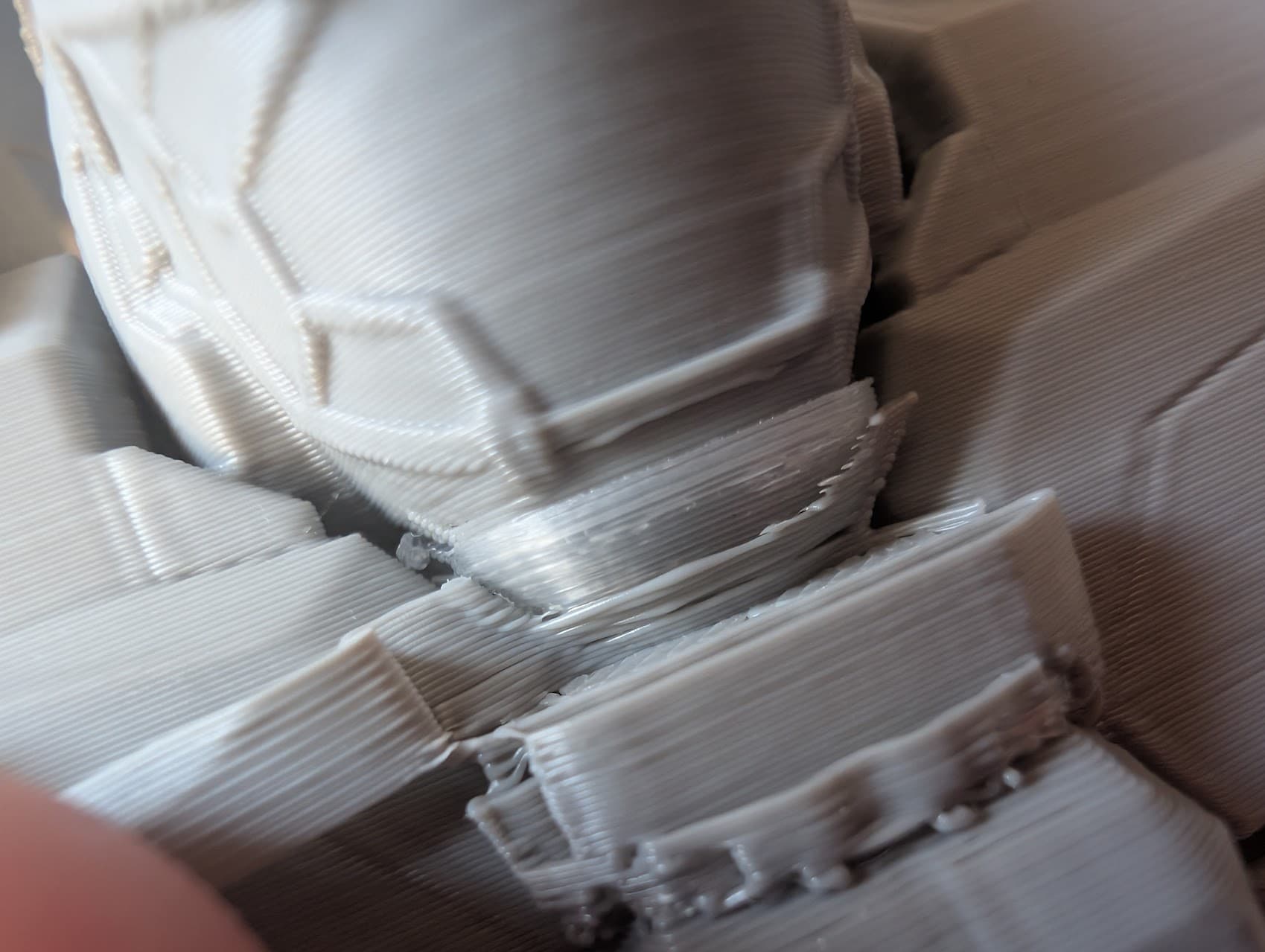
Here, sad as it may be, is the surface I was getting from using “traditional” support methods…
Note the complete absence of handle (should be at the top of this picture) which was long ago lost in removing the support.
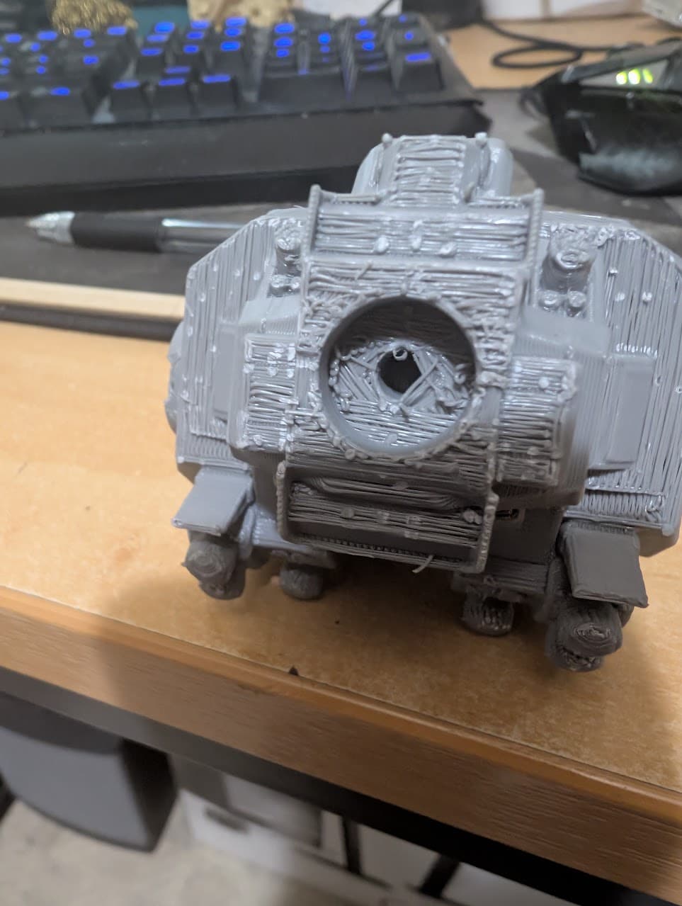
There were other issues with this model…
That central lump isn’t a detail…it’s a tree support. It’s so small and wedged in there so tight I have no way of removing it.
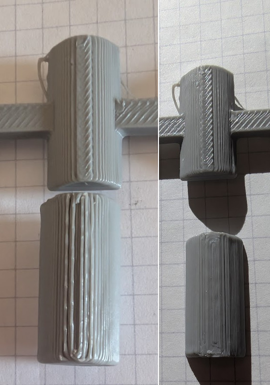
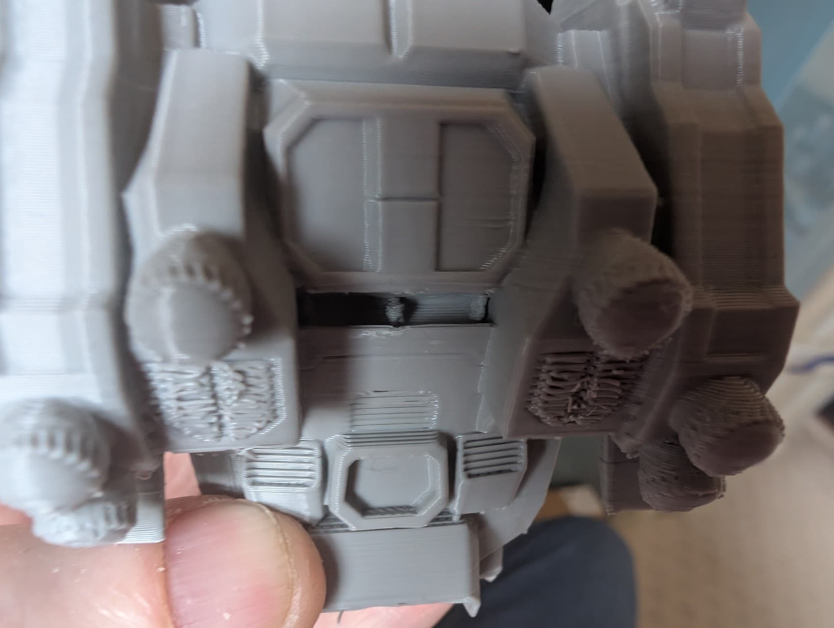
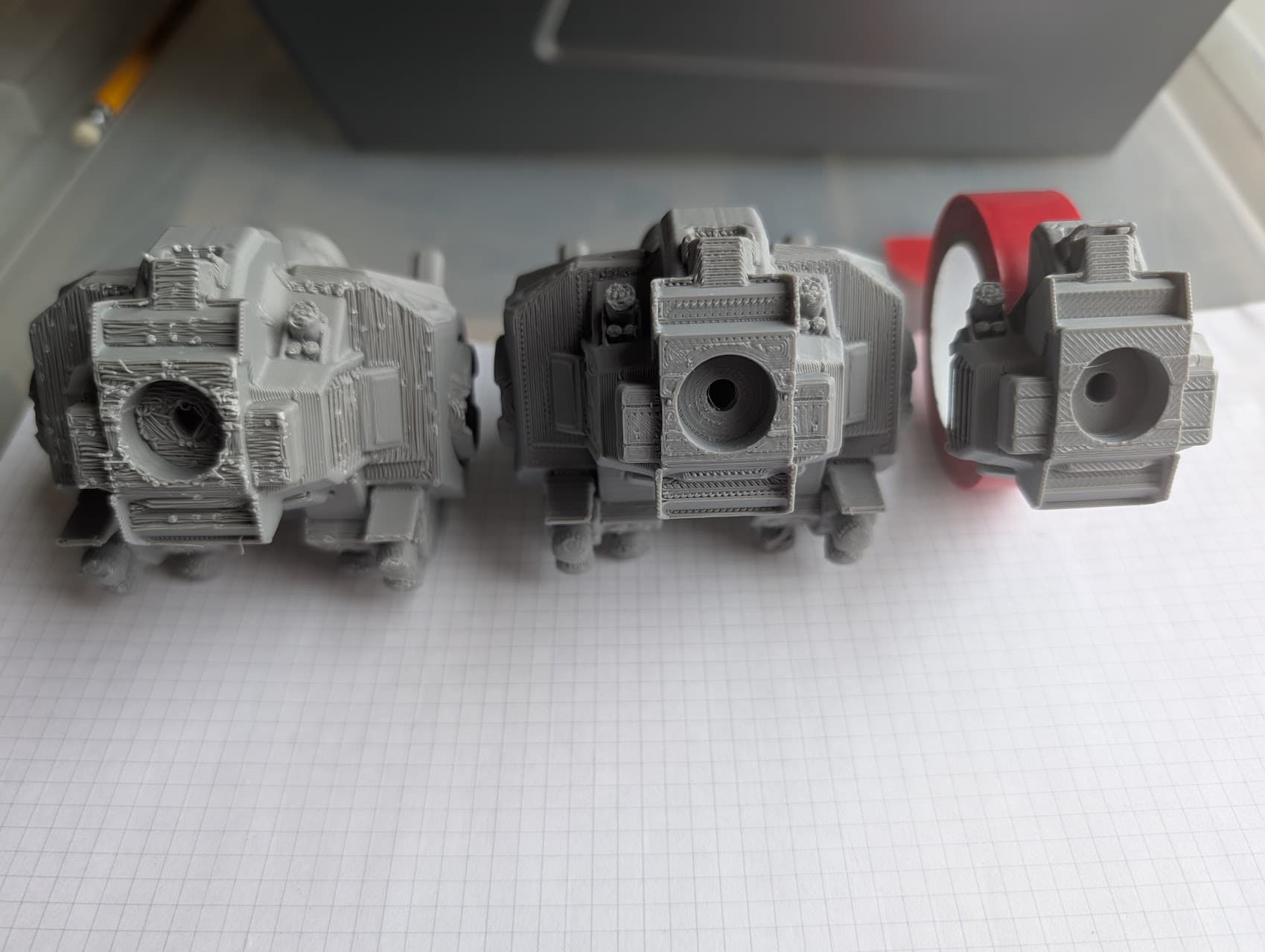
So, a side by side comparison;
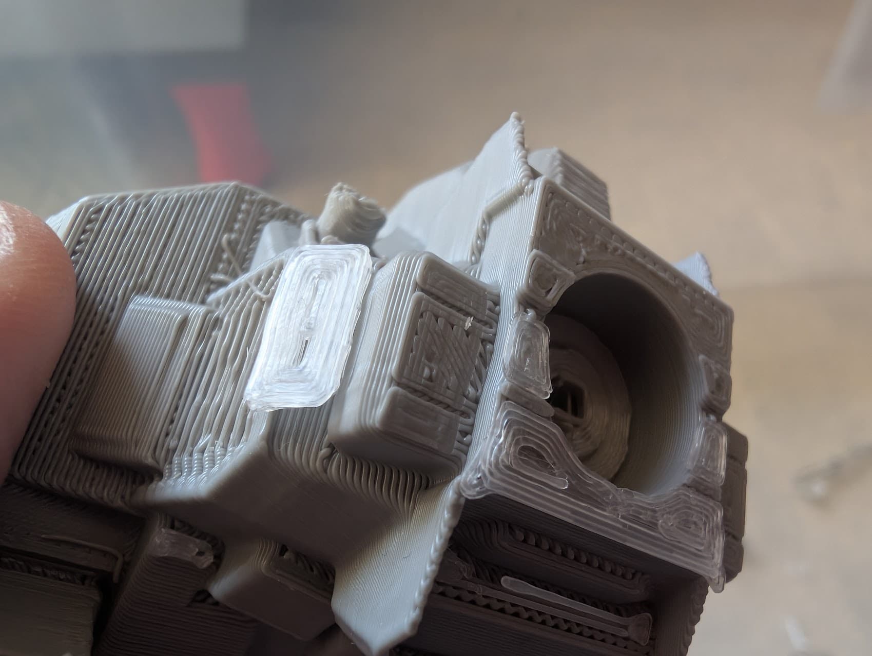
There’s definitely areas where the support filament has worked wonders…remember the stuck “tree” support? Well, this WHOLE VOID was filled with the support filament…and with a tug, it just popped out…
Obviously the same pic shows a failure too, where the support had prematurely come away. If you look closely you’ll also see that the upside down vents are no where near as detailed as the “right way up” one partially occluded by my thumb. This is because I set the X/Y clearance at a massive 0.8 (two nozzles worth) to avoid getting the support physically wedged in places, but it meant that the towers supporting the pods effectively blocked ANY support being given to the vents
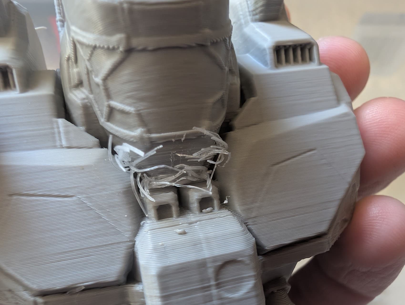
And yet, it still did get wedged elsewhere…
You can see the clear support wrapped snugly around the model’s chin here…
Which sounds ideal, except it led to this…
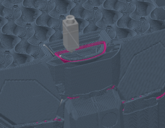
Because behind that chin is a 5mm void stuffed full of support filament - but only a 1mm or so void to be able to remove it through. Colouring the support filament pink clearly shows this problem in the preview page in Creality Print;
So…was it worth it?
Yes…and no. It was worth it in that I learned how the support works and that in certain circumstances, a dedicated support filament with the correct settings can turn a very poor underside into one that is frankly very good preserving in some cases, single layer detail;
.
So for instance, if you absolutely had to have text inlaid for a single layer on the bottom of a shape, using the support filament to fill that void would be a good idea. I’m 100% sure it would just “flick out” at post processing, leaving behind perfect text. That said, on a multi feed machine like the K2+ with CFS…I wouldn’t use the support function to do that; I’d make a separate shape for the text in the design, and just print it in the support filament, leaving a void in the rest of the structure that the support filament could fit in snugly.
Similarly, as a place holder between moving parts, the support filament could be invaluable.
However as seen here, what the support filament cannot cope with is simply this…bad design. @frankjoke had it right (as I’m starting to see he often does) in one of his earlier posts. Sometimes, you just gotta split the model.
Now I’m going to caveat that by saying I’m not just talking about a quick and dirty slice down the middle. If I wanted a seam, I’d have printed a mould. What this model needs in particular is its head removing and maybe some other parts. Get into the design software, import the model and start taking it apart. Hide the joints and add “Plugs and sockets” so that when reassembling the joints are invisible.
Now I paid $36 dollars for this Mech stl, and yes, I find it annoying that for that price the design is…shall we say…optimistic in a product that is clearly sold as 3D printable. It’s going to take time and skill. The head has no obvious place to make the cut, and various other parts (koff 0.83mm handle koff) would be better isolated (not entirely isolated but as part of a small supporting section) and printed separately. In the long run I feel time spent doing that would be more enjoyable, more profitable and more successful than time spent emptying the litter tray, faffing around with support settings and STILL having to spend an hour or two with an army of tools removing all the still-fairly-difficult-to-remove-in-places support material.
Conclusion;
Support material used as support interface (NOT support itself) is a good idea for simplistic shapes that HAVE to be printed in a sub-optimal orientation.
It’s not good in voids that are larger than the entrance to those voids (but then, what is?).
It’s no substitute for good design, and definitely a very poor remedy for bad design.
Suggestions;
If you’re going to use it, use it well! I suggest;
- Set it as the dedicated material for “support/raft interface” and NOT “support/raft base”
- Set Interface Pattern to “Concentric”
- Set “Bottom Interface Layers” and “Top Interface Layers” to AT LEAST 5 (at a 0.2mm layer height, that’s a mm each of both top and bottom interface. If you don’t have the room in your model for that, I’d suggest going back to your design and looking at if that 2mm void is really necessary).
- Consider setting “Support X/Y distance” higher than the default 0.35mm. If your model is very simple you may not have to.
- Set zero values for all these;
Top Z Distance
Bottom Z Distance
Top interface spacing
Bottom interface spacing
But as always - your printer, your print. Both may be different to mine.
Have fun!
GreyArea.