It sure would be nice if the Creality slicer people could work on getting importing magnet holes in a tinkercad stl file to work. Sure I understand that 3d printing a hole in the middle of an object can be troublesome and cause stringing while spitting out filament into a void, however, that space will be filled with a magnet so it’s not a problem. I have tried adding a magnet hole in the slicer but I can’t figure out has to get the hole to be .3mm above the plate. Sometimes the import will work if I join the group as a “Union Group” but when I group the object as a “Bundle Group” to make painting easier it does not work. Or maybe better yet making stl files colored so I don’t have to paint. I’m sure I’m doing something wrong. Any help would be greatly appreciated. thx
It sounds like three separate issues are being mixed here: stringing, using a slicer as a CAD tool, and relying on a non-parametric tool like TinkerCAD for CAD design.
-
Stringing – Solved by tuning filament profile settings in your slicer. There are many YouTube tutorials for this; start with this search: https://www.youtube.com/results?search_query=creality+stringing+fix+solution+retraction+settings
-
Using the slicer as CAD – Slicers operate on meshes. Making geometric edits like adding a magnet cavity is clumsy, because each model or modifier is a separate entity with no parametric links. If you misplace something, your only real option is undo—no persistent constraints or references.
-
TinkerCAD limitations – TinkerCAD is a basic CAD tool, not a professional parametric system. Edits are destructive and not reversible after grouping or combining. There’s no history tree or way to batch-edit multiple features. Compare this to parametric CAD tools like Fusion 360, Onshape, or FreeCAD, where all features are linked and editable via a feature history.
What parametric CAD tools do that TinkerCAD, SketchUp, and Blender can’t:
- Maintain a full edit history so every operation is revisable, rearrangeable, or copied.
- Assign parameters (length, width, diameter, etc.) to any feature.
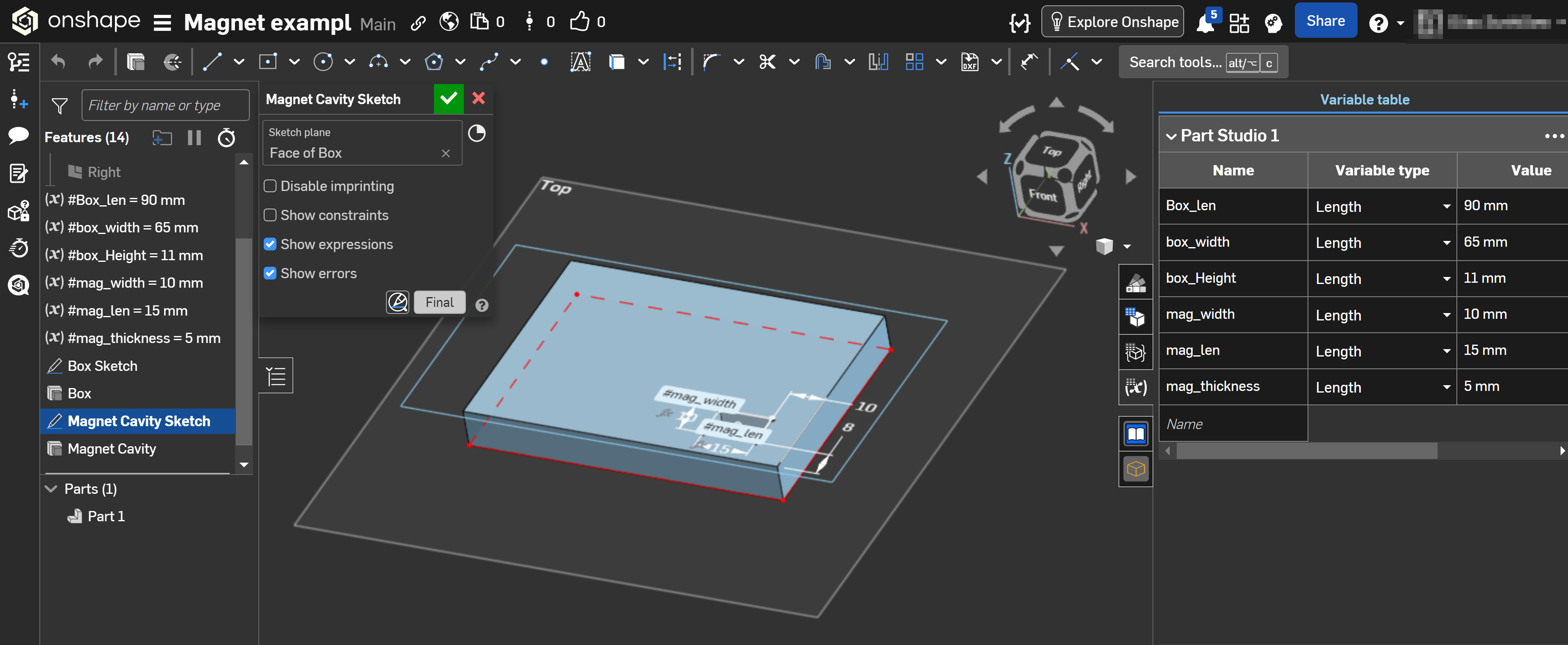
- Use variables and constraints to link dimensions, so changing one value updates all related geometry. Example: if a magnet slot is constrained to the edge of a box, resizing the box moves the slot accordingly without further manual edits.
Example: A simple box with a magnet hole anchored to the bottom-right corner. Define parameters and variables up front, so later edits (like changing box or magnet size) update everything automatically—no manual corrections needed.
For solid tutorials, see Teaching Tech on YouTube: https://www.youtube.com/@TeachingTech/search?query=onshape
This overview covers his recommendations on why OnShape is best suited and covers most of major CAD choices: https://www.youtube.com/watch?v=XHzOzxCQ7MU