Ender 3 V3 KE SPI and GPIO on Nebula pad USB-C connector.

I’m playing with the SPI port that is used to connect the g-sensor. Looks like the USB-C port on the back of the pad is just connections to the SPI bus. My guess is that USB connector and cord are being used as the twisted pair wiring transmits better.

Using a Pi Pico, I’m able to get a byte back and forth and blink a LED. I’ve shortened up wires, wasn’t always getting transmission. Don’t have a logic analyzer and my old scope is too slow and seems to be dying. So marginal results right now, about to dig deeper.

Pinout for connector from reddit:

Mating connector for sensor cable that works.

To transfer using SPI from command line in rooted shell:

cmd_spi transfer /dev/spidev2.0 0x55

Pi Pico is sending back a couple of bytes as well but I haven’t gotten very far yet.

I also see a binary for cmd_gpio, it gives the following brief syntax guide:

cmd_gpio usage
-h/–help : show help info
set_func gpio funcs… : set gpio func
get_func gpio : get gpio func
get_value gpio : get gpio input value
set_value gpio 1/0 : set gpio output value
about gpio:
like the PB18, PA16,
about func:
common_func:
func0: device func0
func1: device func0
func2: device func0
func3: device func0
output0: output 0
output1: output 1
input: input mode
int_lo: interrupt by low level
int_hi: interrupt by high level
int_fe: interrupt by falling edge
int_re: interrupt by rising edge
int_lo_m: interrupt by low level, interrupt is masked
int_hi_m: interrupt by high level, interrupt is masked
int_fe_m: interrupt by falling edge, interrupt is masked
int_re_m: interrupt by rising edge, interrupt is masked
pull_func:
pull_hiz: no pull, keep hiz
pull_up: pull up
pull_down: pull down

So, with SD0, SDA, SCLK, and CS, there may be 4 easily accessible gpio pins available.

I’m wanting to add a MMU, some physical start/stop/pause buttons and status LEDs. I just have to get reliable communication through SPI or GPIO, a polling program on the KE (probably python), a button/LED/MMU control program in C on the Pico.

Thoughts or advice greatly appreciated. I’m a machinist by trade and just hacking my way through C and low level Linux.
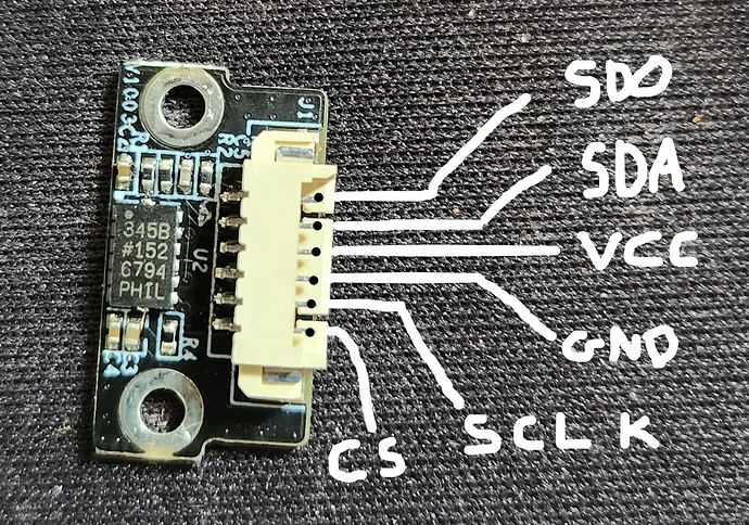
Hello B_Burns,

Is that also I2C “able” (SCL,SDA.Gnd,Vcc) ?

Cheers

Possibly? There are I2C binaries, if I’m remembering correctly. I didn’t even think about trying I2C. It also depends on the SOC pin out, I think. Wish the board and kernel was actually open source.

Wonder if there is a file anywhere that shows pin outs or pin calls that is human readable?

Weird issue I’m having is that SPI is only working every fourth transmission. It is likely a problem in my Pi code as it is getting hung now. It is repeatable and I can get a byte back from the pi before it quits. So, I think I’ve got a clean bus, now I just have to hack on it until both sides talk. I’m using interrupt driven slave SPI on the pi pico, makes it difficult for me to debug.

At the emergency vet, it will be tomorrow before I can look at anything.

Hello B_Burns,

I am not a Raspberry platform user but rather Arduino, as such I am not familiar with programs that the Raspberry can run, but, Arduino has a script that can be run to sniff I2C devices and will give you the address and a few other bits of information regarding the I2C device(s) connected to the SDA and SLC lines.
Maybe there is one such for the Raspberry ?

Cheers.

I played with Picmicro and assembly years ago, right when arduino was starting to take off. Done a fair amount of Linux and RPi since then. My assumption was that the Pi Pico SPI bus would be more likely to work with Linux board running in the KE as it was based on the RPi. The PIO state machine stuff also seemed neat and an easy way to RGB Led and such.

Looks like there is a Pi Pico Logic Analyzer that can be flashed onto a stock board and used:
Sigrok-Pico

Pretty sure I just have a configuration or handling problem that is causing the problem now.

The four try hang has me thinking 32-bit / four byte problem. I’m going to look into what the ADXL345 (the actual g-sensor chip) is expecting for SPI. However it is probably my ugly C code that is lumped together from examples.

Note that the last block of pins contains the spi pins in question. Should be accessible through something like “cmd_gpio get_func GPE” but I haven’t figured it out, not addressing the gpio port correctly, maybe. This would allow direct control of a relay or reading a button.

Output from: cat /sys/kernel/debug/gpio

GPIOs 0-31, platform/10010000.pinctrl, GPA:
gpio-1 ( |bt_wifi_power ) out lo

GPIOs 32-63, platform/10010000.pinctrl, GPB:
gpio-32 ( |TFT_d0 ) in lo
gpio-33 ( |TFT_d1 ) in lo
gpio-34 ( |TFT_d2 ) in hi
gpio-35 ( |TFT_d3 ) in lo
gpio-36 ( |TFT_d4 ) in lo
gpio-37 ( |TFT_d5 ) in hi
gpio-38 ( |TFT_d6 ) in hi
gpio-39 ( |TFT_d7 ) in hi
gpio-40 ( |TFT_d8 ) in lo
gpio-41 ( |TFT_d9 ) in lo
gpio-42 ( |TFT_d10 ) in lo
gpio-43 ( |TFT_d11 ) in lo
gpio-44 ( |TFT_d12 ) in lo
gpio-45 ( |TFT_d13 ) in hi
gpio-46 ( |TFT_d14 ) in lo
gpio-47 ( |TFT_d15 ) in lo
gpio-48 ( |lcd_rst ) in hi
gpio-54 ( |i2c2_scl ) in hi
gpio-55 ( |i2c2_sda ) in hi
gpio-56 ( |TFT_pclk ) in hi
gpio-57 ( |TFT_vsync ) in lo
gpio-58 ( |TFT_hsync ) in lo
gpio-59 ( |TFT_de ) in hi

GPIOs 64-95, platform/10010000.pinctrl, GPC:
gpio-64 ( |backlight_pwm0 ) in hi
gpio-73 ( |ingenic,drvvbus ) out hi
gpio-85 ( |lcd_power_en ) in lo
gpio-86 ( |backlight_pwm0 ) out lo
gpio-89 ( |i2c4_scl ) in hi
gpio-90 ( |i2c4_sda ) in hi

GPIOs 96-127, platform/10010000.pinctrl, GPD:
gpio-100 ( |wlan_reg_on ) out hi
gpio-101 ( |bt_reg_on ) out hi
gpio-104 ( |msc1_clk ) in lo
gpio-105 ( |msc1_cmd ) in hi
gpio-106 ( |msc1_d0 ) in hi
gpio-107 ( |msc1_d1 ) in hi
gpio-108 ( |msc1_d2 ) in hi
gpio-109 ( |msc1_d3 ) in hi

GPIOs 128-159, platform/10010000.pinctrl, GPE:
gpio-129 ( |host_wake_bt ) out hi
gpio-130 ( |bcmdhd ) in lo IRQ
gpio-131 ( |bt_wake ) in hi IRQ
gpio-144 ( |spi_gpio ) out hi
gpio-145 ( |spi_gpio ) out hi
gpio-146 ( |spi_gpio ) in hi
gpio-149 ( |spi2.0 ) out hi
gpio-151 ( |clk32k_out_o ) in lo

Success!!!

Pi Pico’s SPI setup is apparently terrible. See this commentary at Hackaday.io

Ended up using my son’s Arduino and was able to get it to work after a lot of fiddling and false attempts. I’ll post code and details later. I’m switching the led’s in an RGB on and off from the root shell on the KE.

This means G codes that can trigger external actions such as a filament changer and physical start/stop buttons.

Hello B_Burns,

Good to see you have it sorted !

Which Arduino board did you use ? … I generally use the WEMOS D1 mini with WiFi or the ESP32 also with WiFi.

You can then add script to have them create their own Web page for monitoring.
Maybe you might add something like a Sensirion SHtx sensor to give you quite accurate Temperature and Humidity readings (I use the SHT45 myself).

I played with the raspberry things a couple of times in the past but didn’t find them much fun.

Cheers.

Took me a couple of days to get time to work on this again.

I’m using an Arduino Uno R3 clone by Elegoo. I was unable to use pins 0-2 as outputs for the LED, looks like those pins are involved with the UART or something. Anyhow, this program is the bones for sending back and forth small amount of data, flipping a relay, or showing a button press. You could definitely run humidity or temp sensors with this. You could probably even setup Fluidd to display them on its web page.

I’m going to use it to drive a 3d Chameleon MMU. Also want pause/start, stop, e-stop, and filament change buttons. Will have an RGB led as a ‘Christmas Tree’ indicating machine status. (Machinist in me is bothered by the lack.)

VERY IMPORTANT!!! I think the board on the KE is 3.3V, the G-sensor is. The Arduino is 5V. The output on the Arduino has to have a voltage divider or it can fry the board in the printer. So, pin 12/MISO must have a voltage divider where SD0 from the printer is being driven at a lower voltage. I’ll put together a schematic if there is interest.

Forum won’t let me upload a .ino file, and not sure if I’d get kicked for renaming. This answer on stack exchange was my source for working SPI.

Code follows:

#include<SPI.h>
#define led_proto 4
volatile boolean received;
volatile byte receivedData;

ISR (SPI_STC_vect)        //Interrupt routine function 
{
  receivedData = SPDR;   // Get the received data from SPDR register
  received = true;       // Sets received as True 
}
void setup()
{
  Serial.begin(115200);
  SPI.setDataMode (SPI_MODE3); // KE is mode 3
  pinMode(MISO,OUTPUT);   //Sets MISO as OUTPUT
  SPCR |= _BV(SPE);       //Turn on SPI in Slave Mode
  received = false;
  SPI.attachInterrupt();  //Activate SPI Interrupt
  pinMode(led_proto, OUTPUT); //LED, pins 0-2 not working as outputs possibly due to SPI setup
}


void loop()
{ 
  if(received) {                        
    SPDR = receivedData + 1;    // send back receivedData with a change
    received = false;
    if (receivedData == 1) {
      digitalWrite(led_proto, LOW);
        }
    if (receivedData == 2) {
      digitalWrite(led_proto, HIGH);
       }
    Serial.print(receivedData, HEX);
    Serial.println();
  delay(1000); // do stuff
  }
}