Hi there, I want to replace the stock filament runout sensor on my K1 Max with a BigTreeTech SFS v2.0 sensor. I read a lot of articles and watched a lot of youtube videos on the subject but not everything is clear yet. Okay, so it seems that just using one of the two sensors of the SFS is relatively easy; just use the leads from the original sensor so the connection is made to pin PA15 on the motherboard. But I would like to use both sensors (movement and runout) which means I would have to make another connection to pin PA10 on the printhead board (which means attaching a new wire and leading it through the chain). Is that correct so far ?
2024-08-12T22:00:00Z
K1 MAX_电气接线图_V1.4_1723512344274_z4yzh.pdf (343.5 KB)
Wrote to Creality support and they sent me the above pdf
That sounds right but, the software is going to need to know how to interpret the signal provided…
You do not need to use both outputs to achieve block filament and runout sensing.
The pulse output will achieve both functions. you would have to modify the either the printer.cfg or gcode_macro.cfg files for the new filament detector.
Thanks for the remarks ; as soon as I have some time I will try to test this setup.
There is a person on Youtube who has already implemented this, and I tried to reach out to her, but no respose so far …
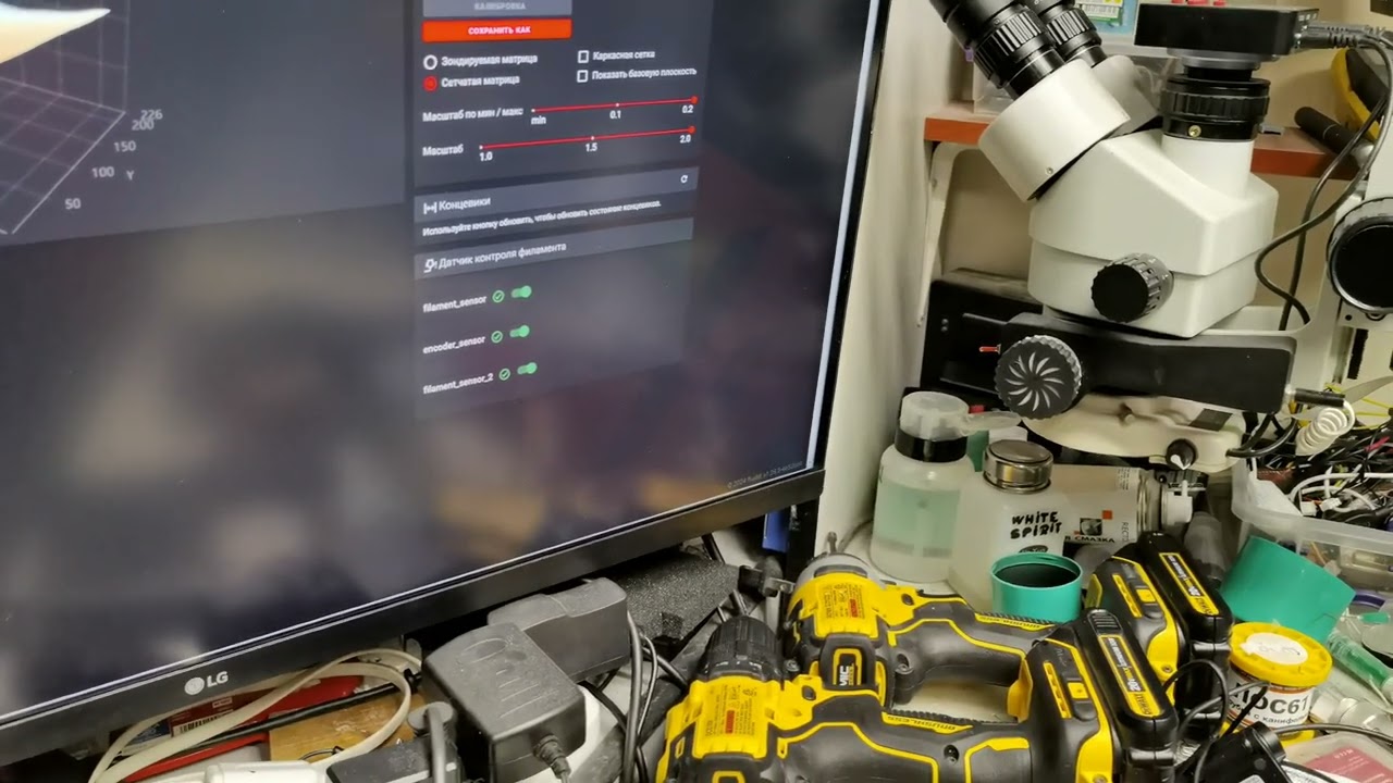
I’m going to do the same but on a with a v1 smart filament sensor.
I saw this Thread maybe it can help you?
I am the author of this video). The output of the filament presence sensor must be connected to the PC15 pin (as on the old sensor), and the pulse output must be soldered, for example, to the PC7 pin on the board… I connected it like this. And here are my settings in printer_config
[filament_switch_sensor filament_sensor]
pause_on_runout: true
switch_pin: PC15
runout_gcode:
{% if printer.extruder.can_extrude|lower == ‘true’ %}
G91
G0 E30 F600
G90
{% endif %}
[filament_motion_sensor encoder_sensor]
switch_pin: PA7
detection_length: 12
extruder: extruder
pause_on_runout: true
runout_gcode:
{% if printer.extruder.can_extrude|lower == ‘true’ %}
G91
G0 E30 F600
G90
{% endif %}
Hi Karen,
Thank you for your response ! 
Pin PC 15 is the material break detection (same as the old sensor) on the top of the mainboard.
Can you point out pin PA15, please ?
regards
Erwin
it was a long time ago, I don’t remember. You need to find a free microcontroller pin on the bottom board according to the datasheet and connect two sensor signal pins to these pins. I connected them to the PC15 and PA7 pins
Thank you for responding so quick … I will investigate further …
Karen. Were the changes in printer_config the only changes you made, or are software changes needed also?. If so, any details you have would be great, thanks.
I have looked into this as I have a DXC extruder and would like to keep using it as the runout sensor, and the SFS 2.0 as the pulse sensor. I decided to solder a male connector to the board on RS458 and use the ground and one of the pins. I will be installing it this week and let you know how I get on. I will attach a PDF with the wiring diagrams etc.
K1_SFS_Wiring_Final.pdf (208.3 KB)
well that didn’t work. you cannot use the RS485 header in that way. I think I may need to use PC7 and solder directly to the board.
so I soldered a 3pin connector to PA1 ( the top one ) and PA7 ( the bottom one ) , but none of them worked for me. I think the board is missing the resistors. ( Signal was there, and so was ground and power , the sfs 2.0 did power up) , but I just got no response when inserting filament. Ended up making a cable and connecting the motion wire ( green ) to the original filament sensor on PC15 , and leaving my DXC connected to the tool head. The resistors that need to be solders are tiny. There is some explanation here - Creality K1-Series Btt SFS V2 Mount by anavrin72 | Download free STL model | Printables.com