Noticed this when printed long parts (10 mm high) oriented along the Y axis: the far end was 1 mm higher than desired, the front was 1 mm lower than desired, and only the middle was the correct size.
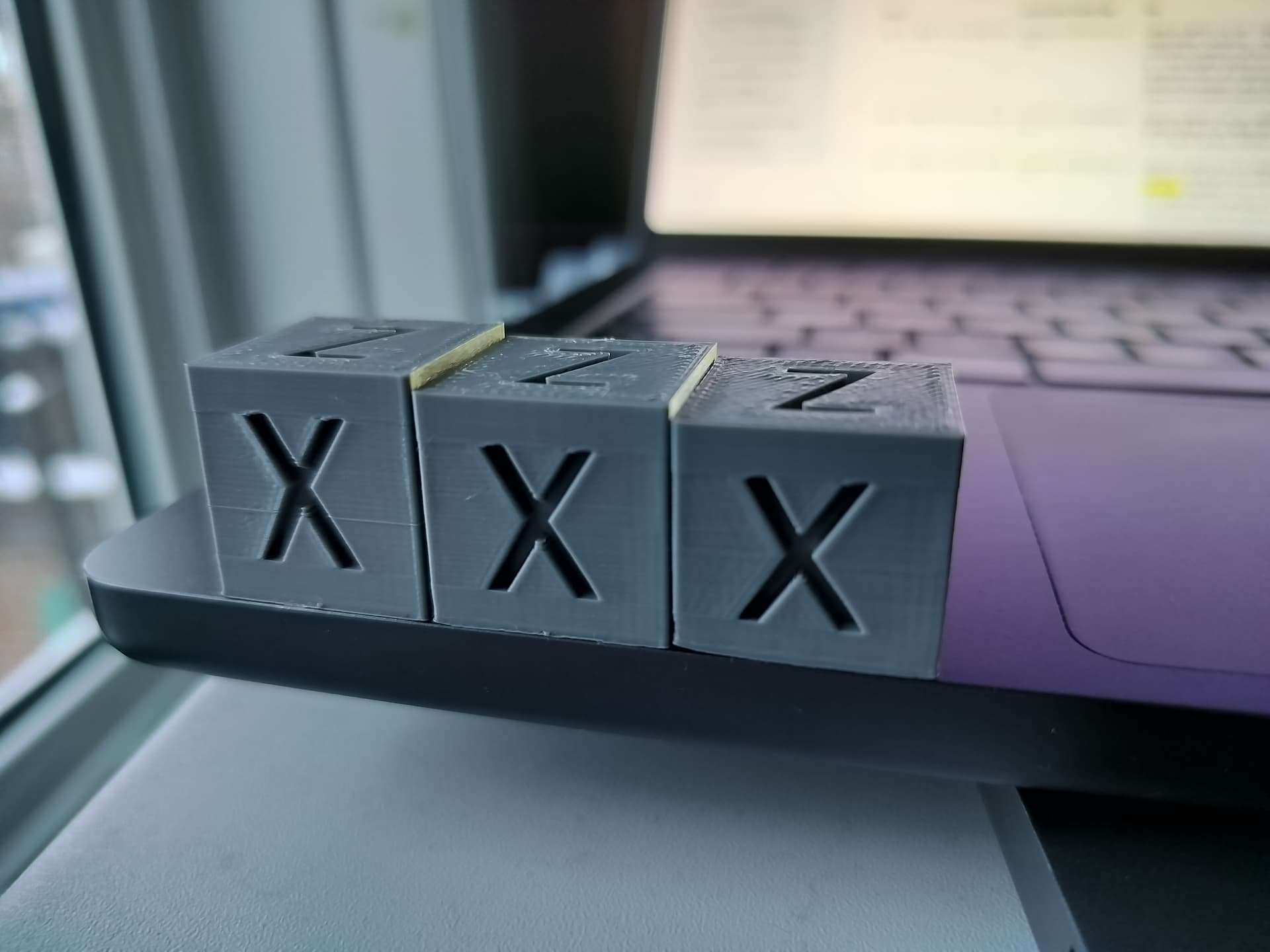
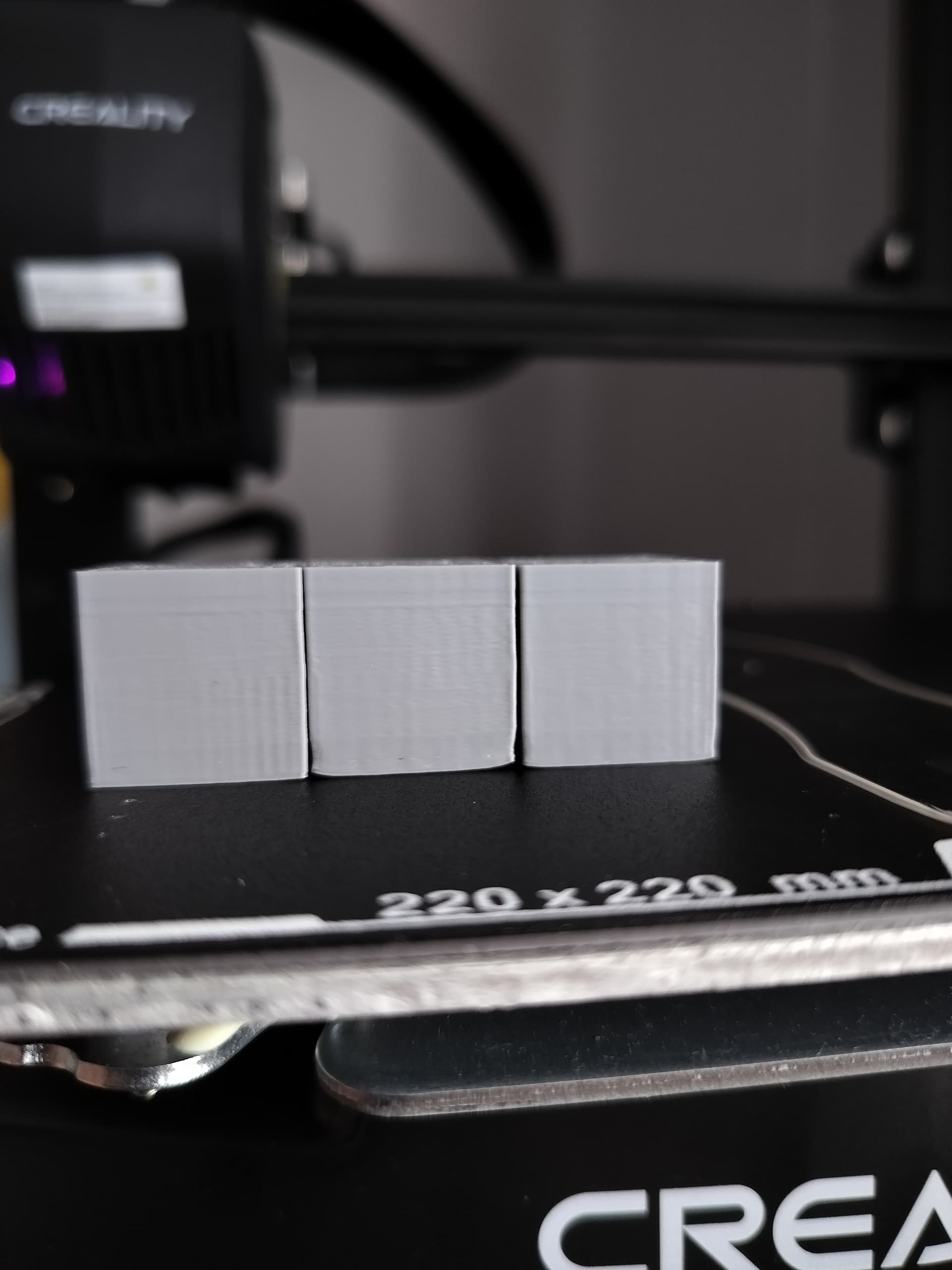
Now confirmed that with 20 mm calibration cubes located in 3 places along the Y axis: the difference is still the same: 19 mm, 20 mm, 21 mm. X and Y dimensions are as expected.
The bed is leveled, test squares look good, nothing seems to wobble. It looks like the layer height correlates with the Y coordinate.
What could be the reason?
Squareness of the Z gantry in relation to the bed? Mine was about 2° off with the gantry leaving forward.
I do have some deviation of the gantry. But shouldn’t it affect all layers equally along Y?
Which slicer are you using as I am going to try this out in the morning. I doubt my machine does this but it would be a good investigation.
I’m using the latest Cura. Will also try some skew tests tomorrow, maybe it’ll tell something.
Its odd that the tops are level but they are differing heights.
1 Like
Small update: sliced those cubes with Creality Print, the result is the same.
And, actually, tops are not level. They have the same inclination, the front side of each cube is a bit lower than the back side.
I can’t replicate it, didn’t take a photo but all 3 were the same height. Vernier measured 20x20x19.9
1 Like
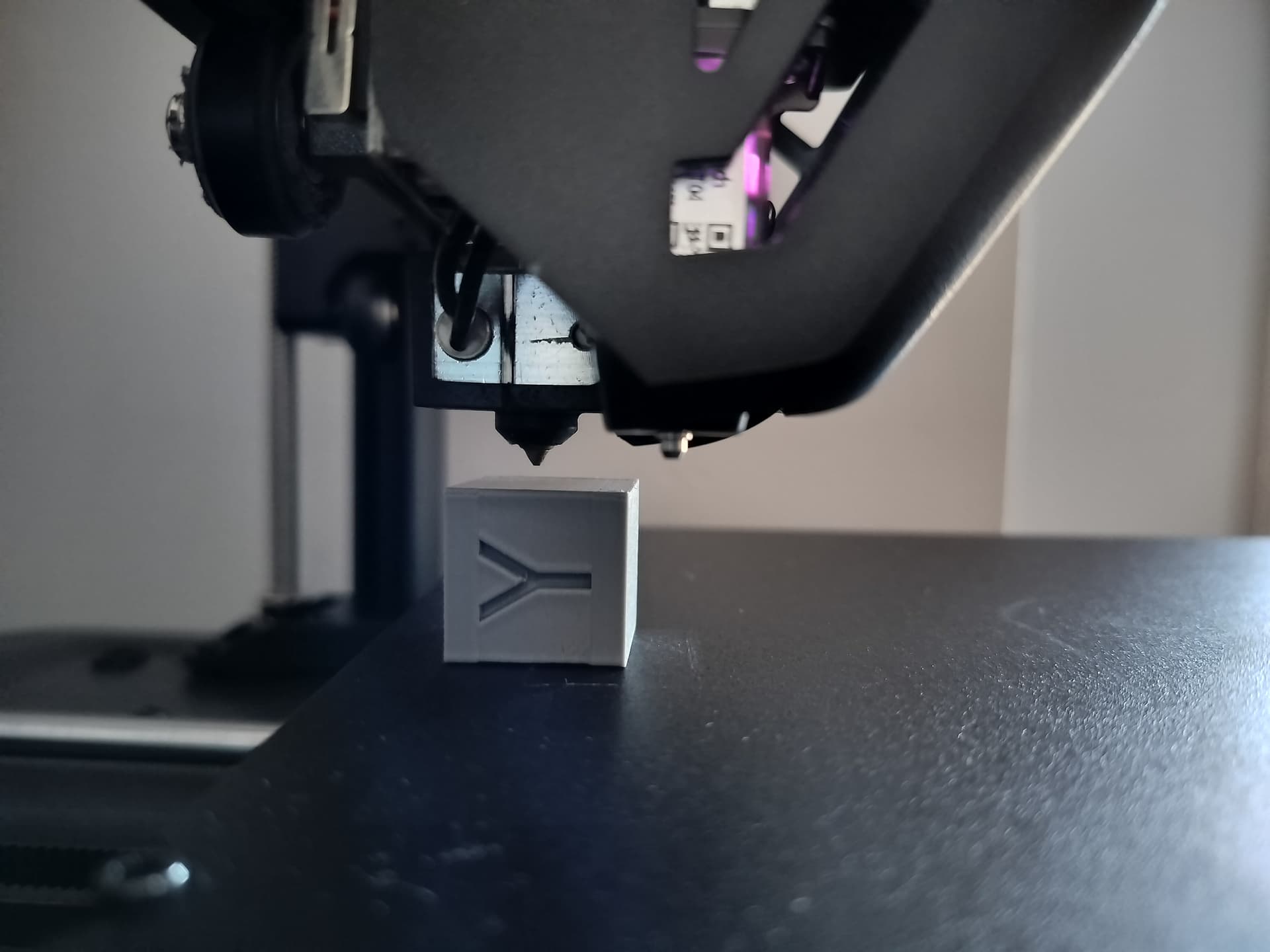
One more experiment: positioned the nozzle on top of the cube at Y=10, then moved it to the other side, Y=210. The nozzle now 2-3 mm above the cube.
Will need to check the bed mount, rods, etc. once again.
2-3mm is an awful lot. If it were a few 10ths of a millimetre I would say mechanical issues but this is something else. Can you try Orca? Not trusting CP6 at the moment.
I don’t think it’s a slicer issue: the unevenness is seen even when simply moving the bed. Weirdly enough, there’s no such a large difference between front and back at Z=0.2. So it appears like the bed is leveled at Z=0, and is not at higher Z values.
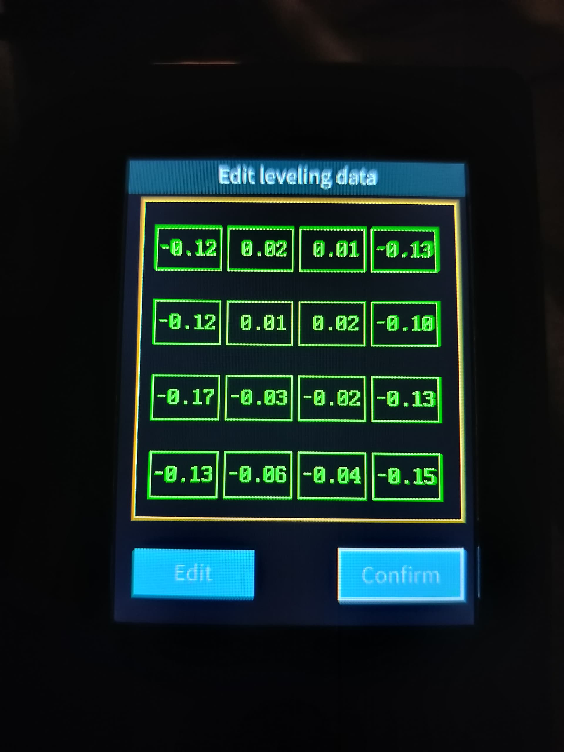
What does your bed mesh look like?

Front to back you have over 3mm of slope and even more from front left to back right, that is more than the autolevel can cope with. I think you need to look at shimming that bed. On my ender 5 plus I replaced the springs with silicone spacers to get that level, I’ve read of people also doing it on a V3SE/KE bed, tighten the screws until you get it level or modify the existing bed spacers, I did this once, but I do have a machine shop and a supply of 10mm delrin. If you aren’t technical is it in guarantee to get it replaced?
1 Like
Yeah, I realized something is wrong as soon as I posted the mesh. The slope is apparent.
Appreciate your help!
So it was a leveling problem indeed. Now there are some quality issues (probably speed was too high, and the bed is a bit dirty), but at least the height is now even.
1 Like
Impressed how flat you have got that bed, well done, any pointers that you might give to help others would be appreciated. As you say the rest of your issues are bed cleanliness, filament tuning.
I started off by sanding the spacer from the highest corner, but then decided to use a less invasive approach, and printed spacers from here: https://www.printables.com/model/1045123-ender-3-v3-seke-bed-spacers.
With a bit of trial and error I found the right heights for each corner. It’s really better to do as the author suggests: print 2 mm spacers for each corner and then go from there.
Do you suggest to calibrate the extrusion now?
1 Like
I would start with temperature and retraction especially for TPU, flowrate also but you can do that on-the-fly by seeing how the filament lays down, if it ripples lower the flowrate. TPU is a pain to print, 10°C each way it will string, too small retraction it will string, I’ve nailed it on my V3SE and it pretty much only prints that now, oh to be spoiled for choice of printers.
1 Like
1 Like