No, I haven’t returned my K1 Max. It is a great printer, except my sample of K1 Max… it’s not suitable for printing cylinders. It has a closed chamber and a 300x300mm build size, which are hard to find in other affordable options.
However, because I needed to print many small cylinder objects, I had to purchase several Bambu Lab printers. It’s important to note that Bambu Lab printers have a 0.2mm nozzle size, while the K1 Max has a 0.4mm nozzle size. This difference was a game changer for me.
Just like you need small, medium, and large screwdrivers for serious work, I’ve found that each printer has its unique use. The K1 Max is like a large screwdriver, while the A1 and A1 Mini are like mid and small screwdrivers. I’m eagerly looking forward to buying the K2 Pro. After dealing with the K1 Max for almost 3 months, I feel prepared for anything.
Bambu Lab is great and works right out of the box, but there’s not much to learn. On the other hand, with Creality printers like the K1 Max, you soon become skilled in printer maintenance! :)"
Since I see that many people have the same problem, it’s my turn to write what the problem was and, of course, how it was solved.
Creality support was relatively fast. They responded within 24 hours mostly. What I didn’t like was that they asked for too much data. Receipt, as if the printer could be out of warranty, photos, video, STL file… all of that should be saved, it’s serious work, and it’s not my job to do it. I honestly paid for the device and I want it to work as soon as I take it out of the box!
Then again, I can’t blame them either, all kinds of people have no idea and want to print nonsense. Theirs is that the problem has been identified.
First, they gave me a link to some unrelated wiki page, as if I hadn’t tried all that already.
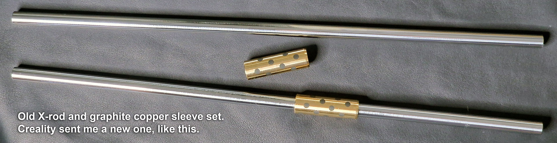
Then I replied that I already tried all that, sent a comparison print, K1 Max and Bambu A1 and then they offered to send me an “X-rod and graphite copper sleeve” set. Of course, the sliding bearing is not copper but brass, but Creality support calls it that.
The repair kit arrived in maybe a total of 7 days from their last email asking me for shipping information, which of course I sent them right away.
The set of spare parts arrived by DHL, so it really couldn’t have been faster and I didn’t pay anything. It was 100% free for me.
When the set arrived, I carefully inspected it and saw that the bearing sliding over the rods was incomparably easier and smoother than with the old one.
I disassembled the X and Y axis, cleaned the graphite dust and the oil I used for lubrication, and replaced the sliding bearings and the X-axis rods. At first glance, I could see that the X-axis assembly, the 3D print head was running much smoother than before.
I assembled the printer, did the X/Y Homing and then did the Input Shaping and Bed Leveling.
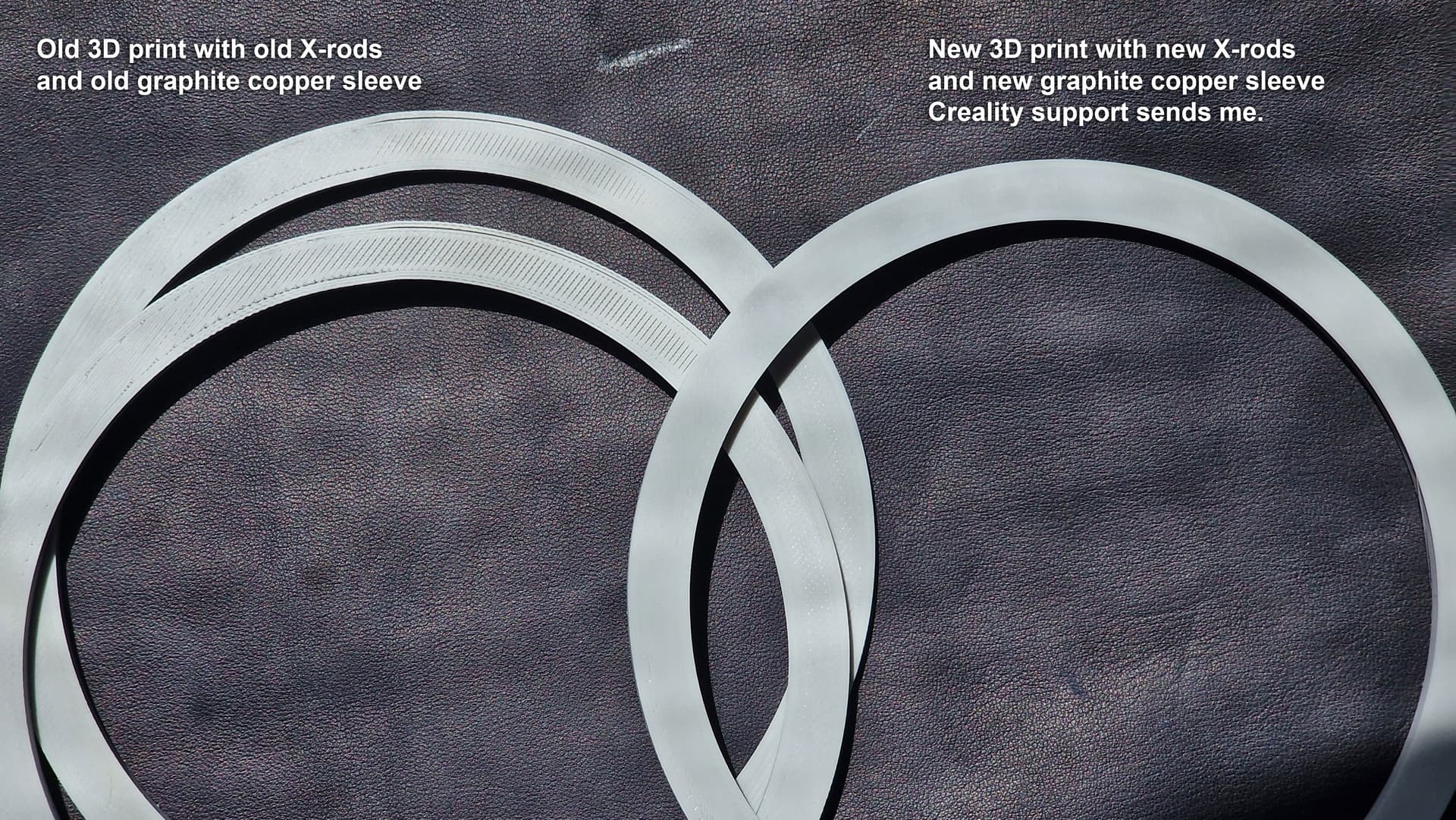
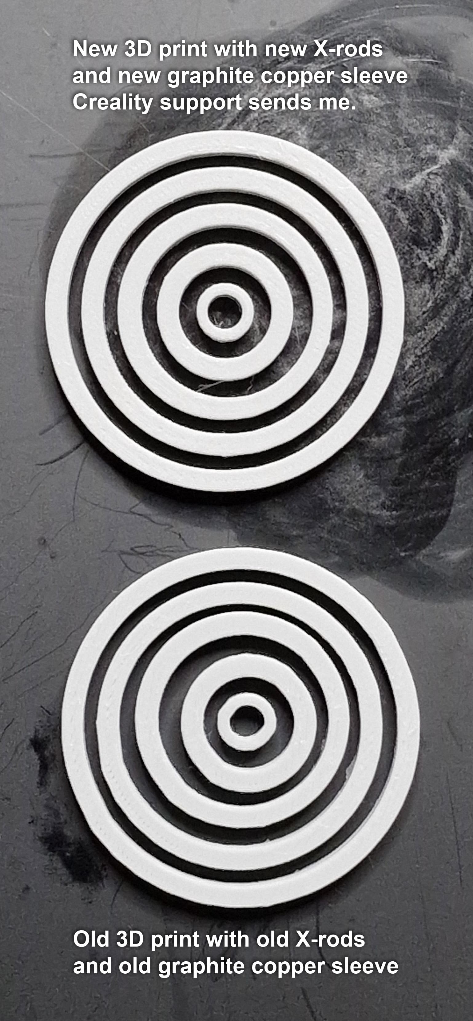
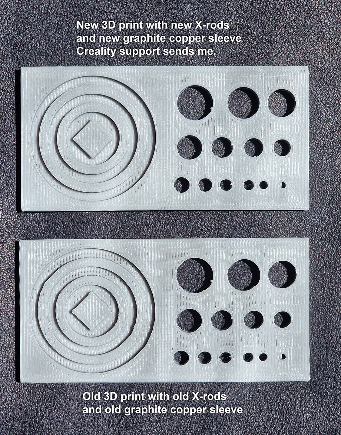
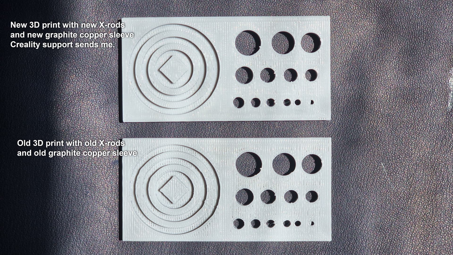
From the very start with the new set, the printer ran noticeably smoother and the quality of the printed circular shapes was drastically improved.
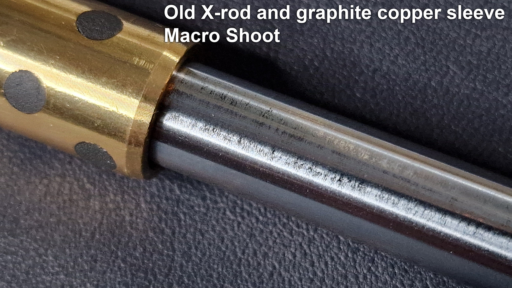
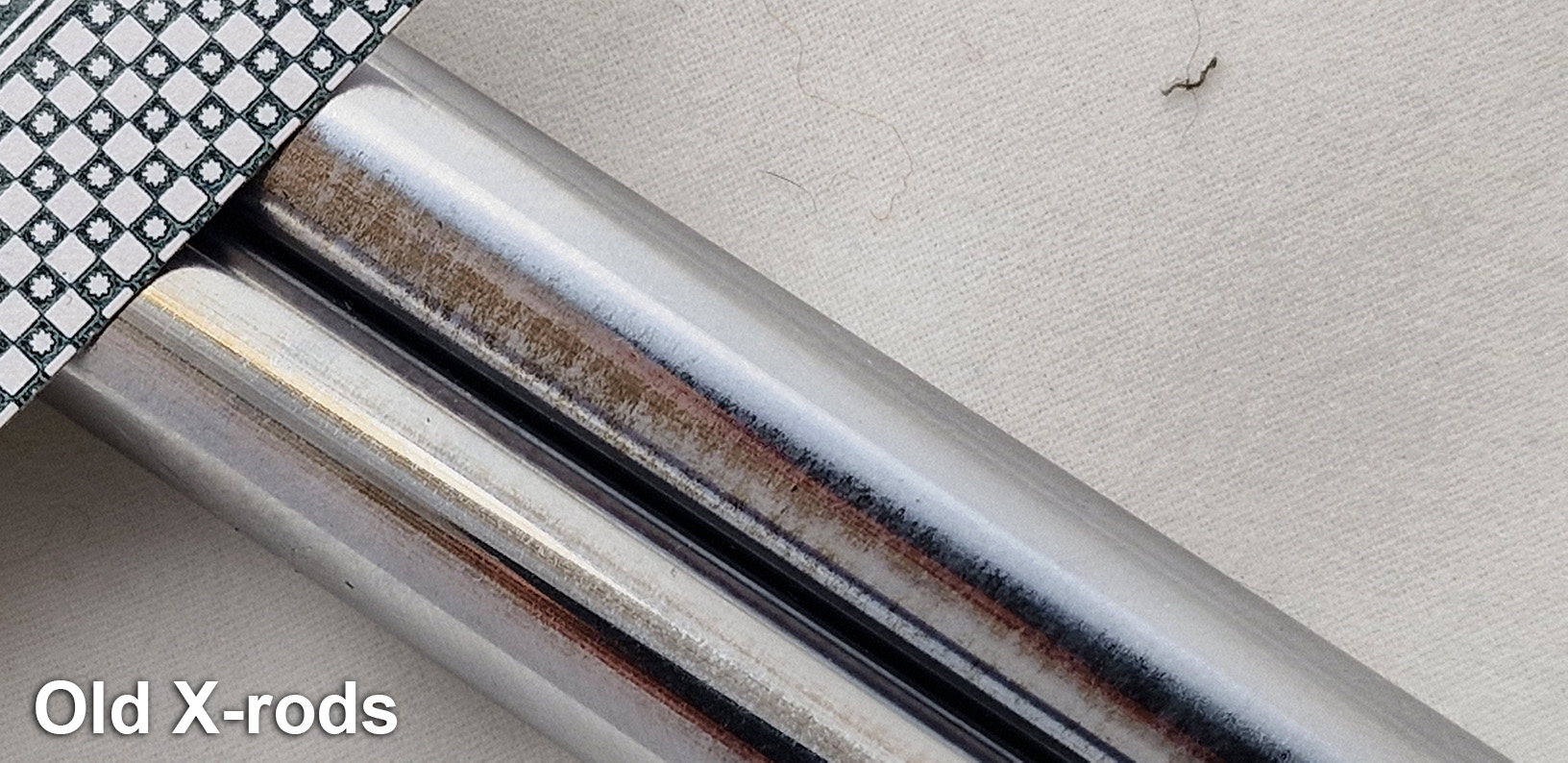
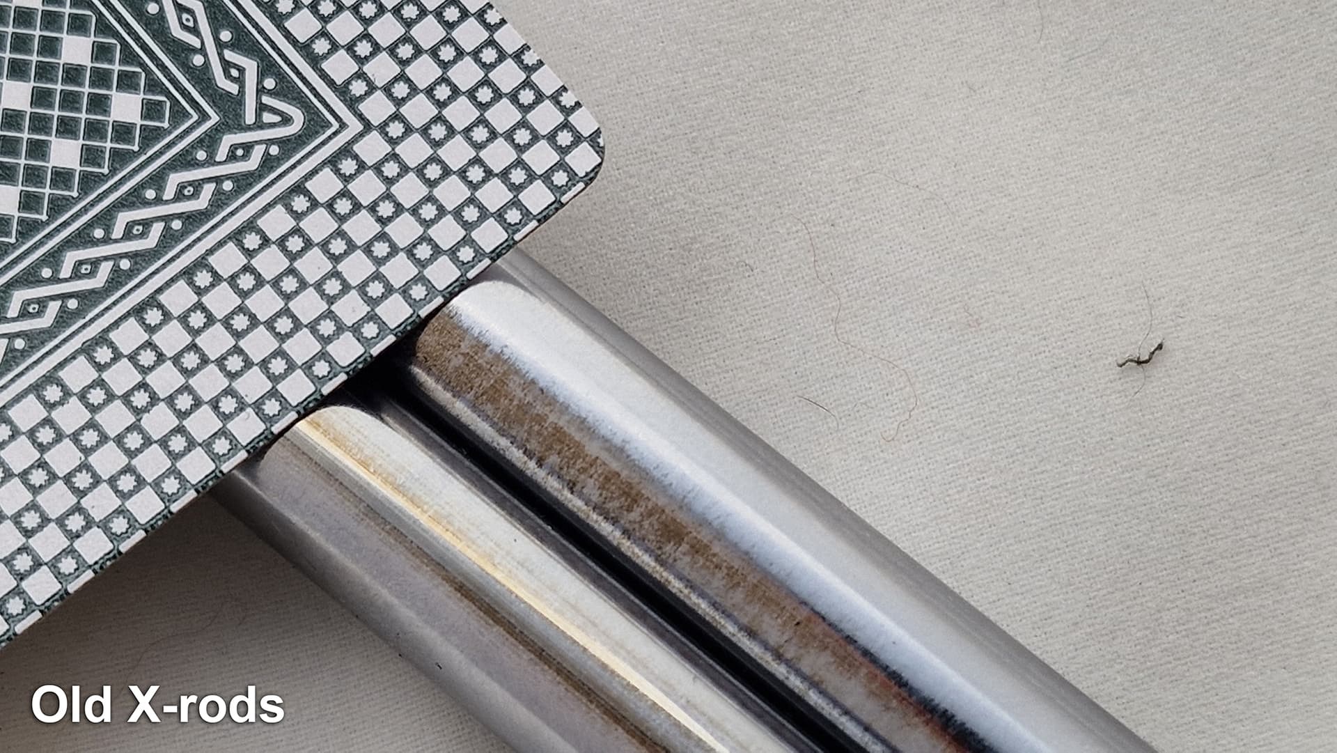
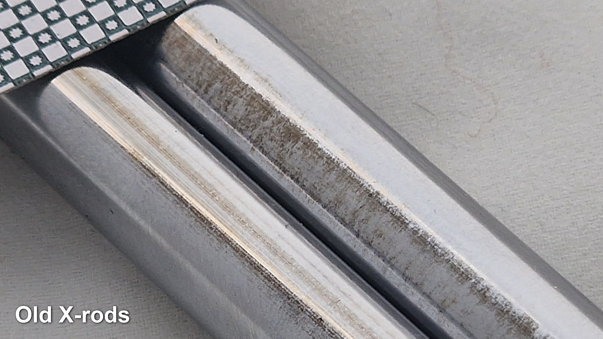
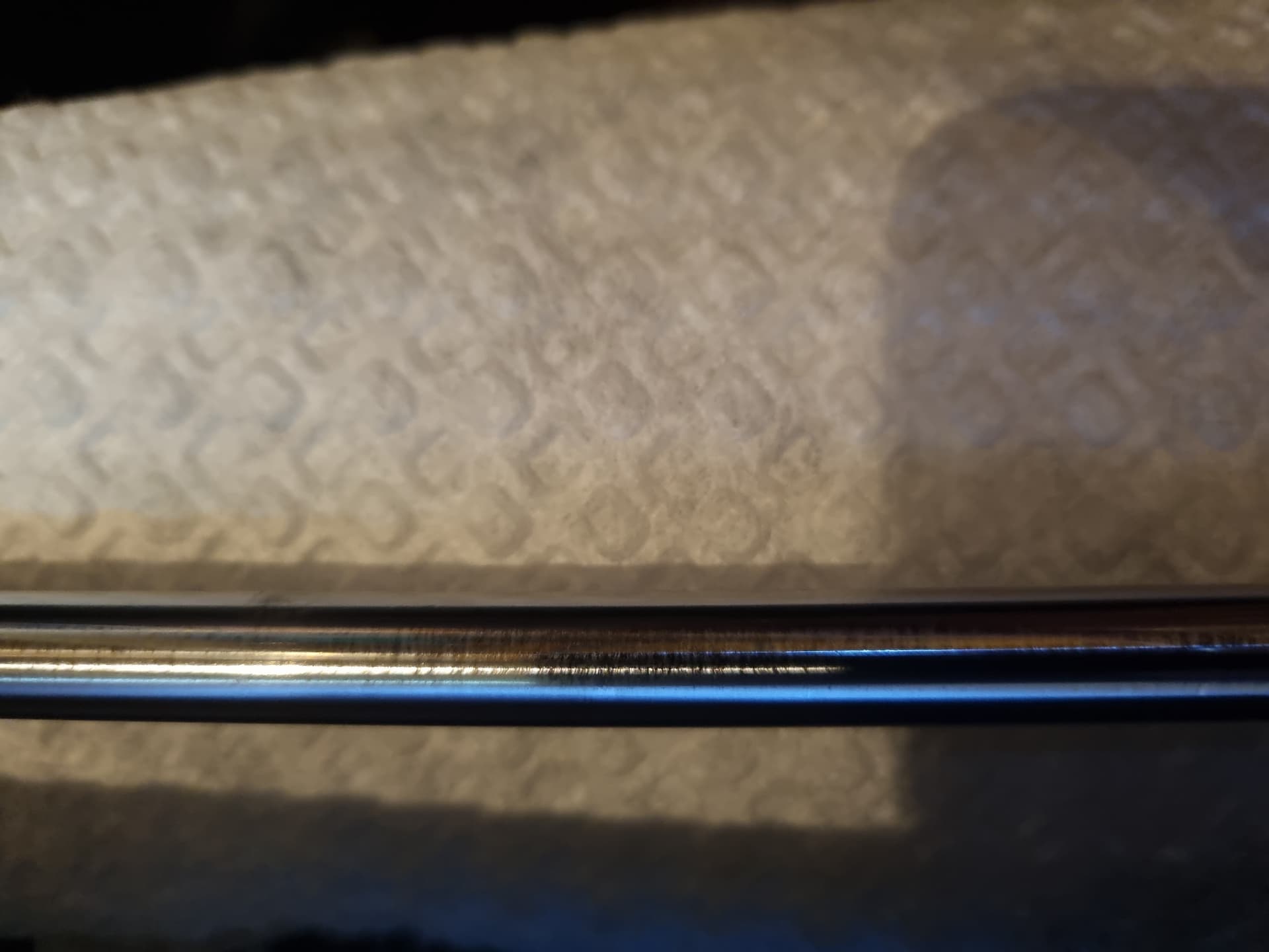
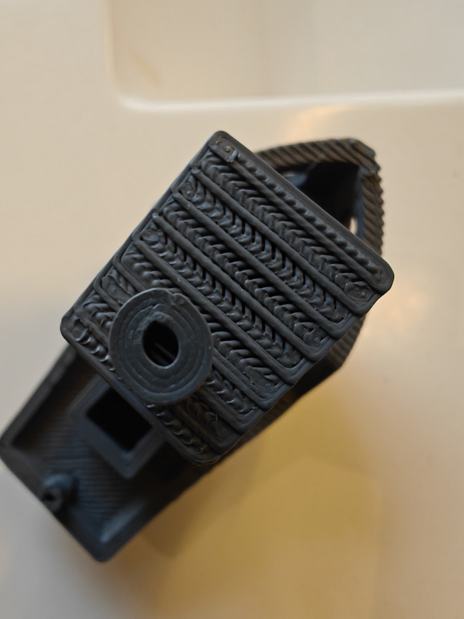
A detailed analysis of the surface of the original X-axis rods shows that they are factory-made in a bad way. The surface is probably chrome plated and mine had a lot of micro cracks. I don’t think it was polished well before chrome plating and then you get that kind of small micro cracks in the surface.
Everything can be seen in the photos. Unfortunately, this is difficult to see while the rods are mounted in the printer. They have a small diameter, they reflect everything vividly and when the light of the internal LED strip is turned on, it makes it not possible to see it with the naked eye. Maybe it would be seen in some special conditions or who knows what to watch.
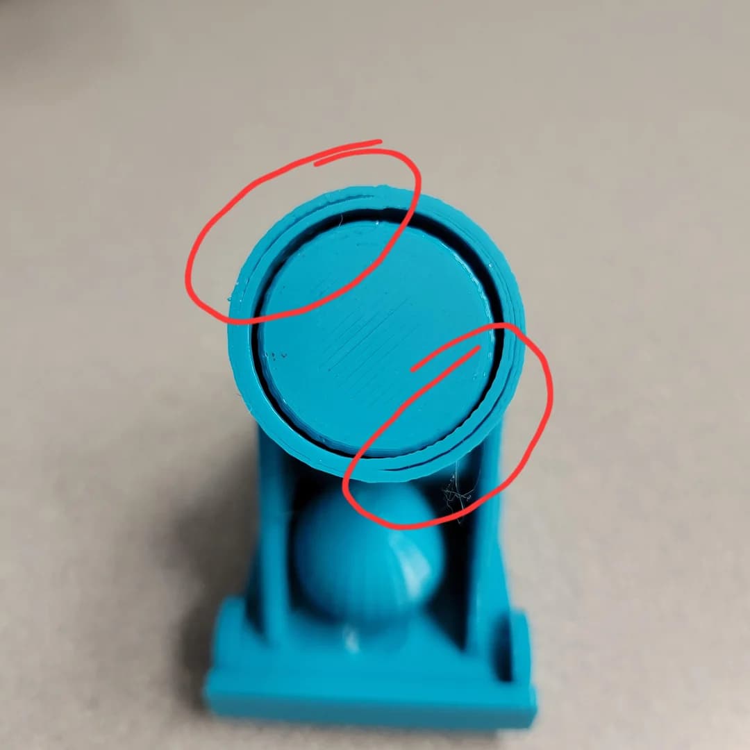
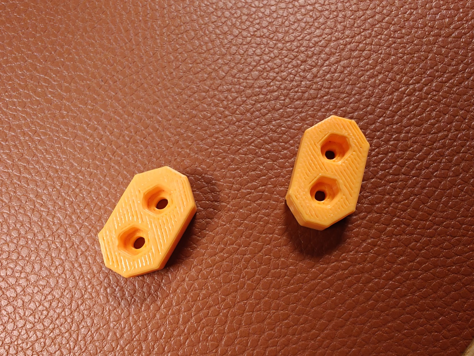
Attached are photos of the original prints and prints with replacement parts.
I hope this helps anyone who has the same problem to solve it!
And please, don’t put any oil on the X axis!!! You could only make a thick gooey which will significantly harden X motion!
I thoroughly check everything and the X-axis slides best when rods are perfectly clean! Graphite bearings do the magic!
You may have just solved the problems of a lot of people! You say you tested the rods and to not put any oil, that is not even Singer oil or PTFE-Dry lube?
Yes, you could try it yourself. It slides very well with those graphite powder circles bushing all around. I guess even a slight amount of oil on the x-axis rods would ruin smoothes because when combined with graphite dust, it forms thick viscose fluid, which limits continuous smooth sliding.
I used Juki sewing oil, which is much better than any Singer oil, but as I told you, it’s not worth it.
My problem was initiated with rods whose surface was “cracked” with maybe some kind of oxidation or even some “surface rust” before the chrome plating process and the printer had a problem with smoothness when the Y movement was “crossed” with the X movement.
At that moment, as X-axis rods weren’t smooth enough, moving was not synchronous and those “bumps” were formed. I don’t have any other explanation.
TL;DR: The excessive friction along the X-axis caused by imperfections on the rods, combined with the natural elasticity of the belts causes a kind of “High-pass filter” effect on the movements of the X-axis.
Interesting, after reading about your experience I immediately cleaned my X rods with Isopropyl alcohol, but they were as always, about twice as hard to move in the X axis than the Y axis, then I started to notice my Y rods were perfect while the X ones were like yours.
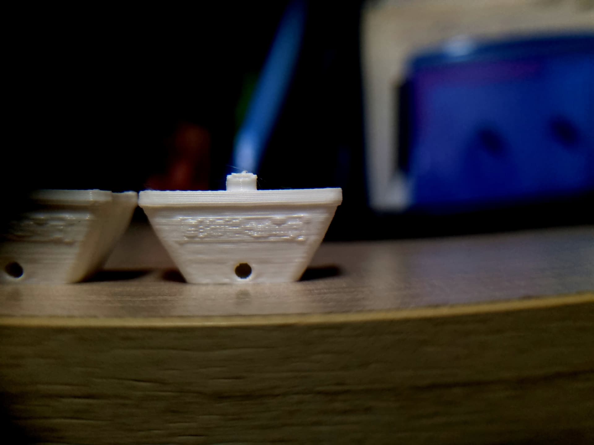
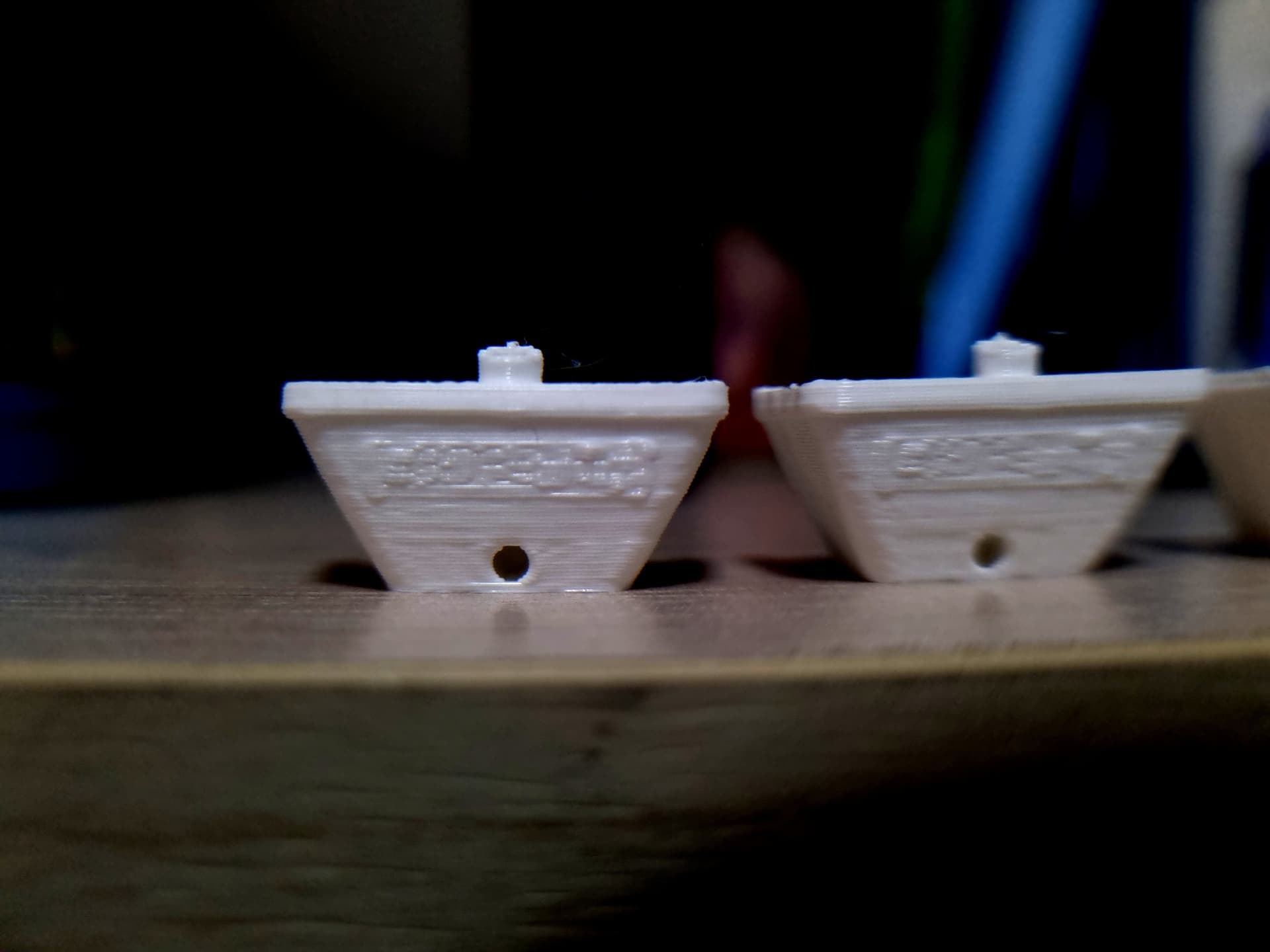
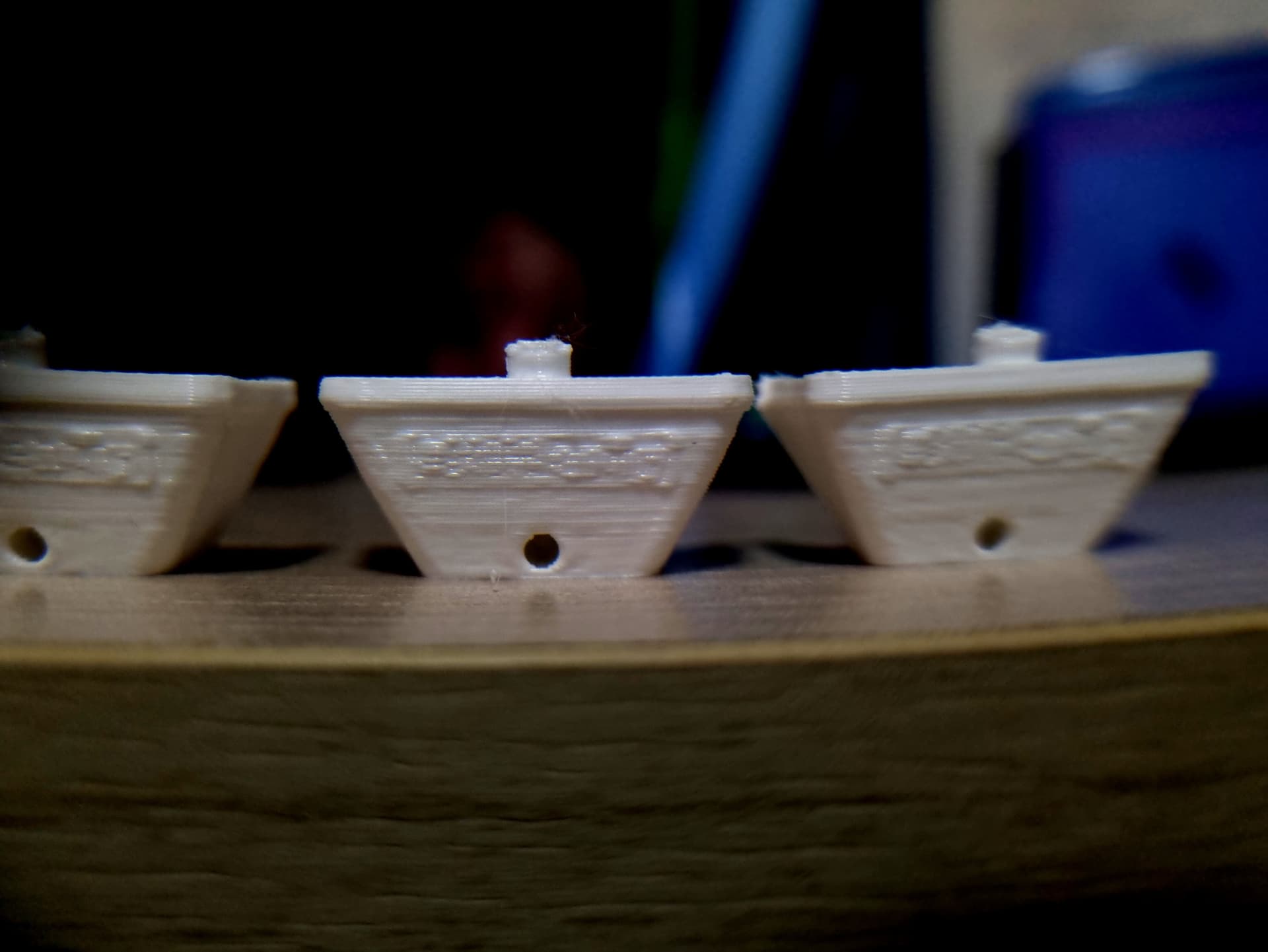
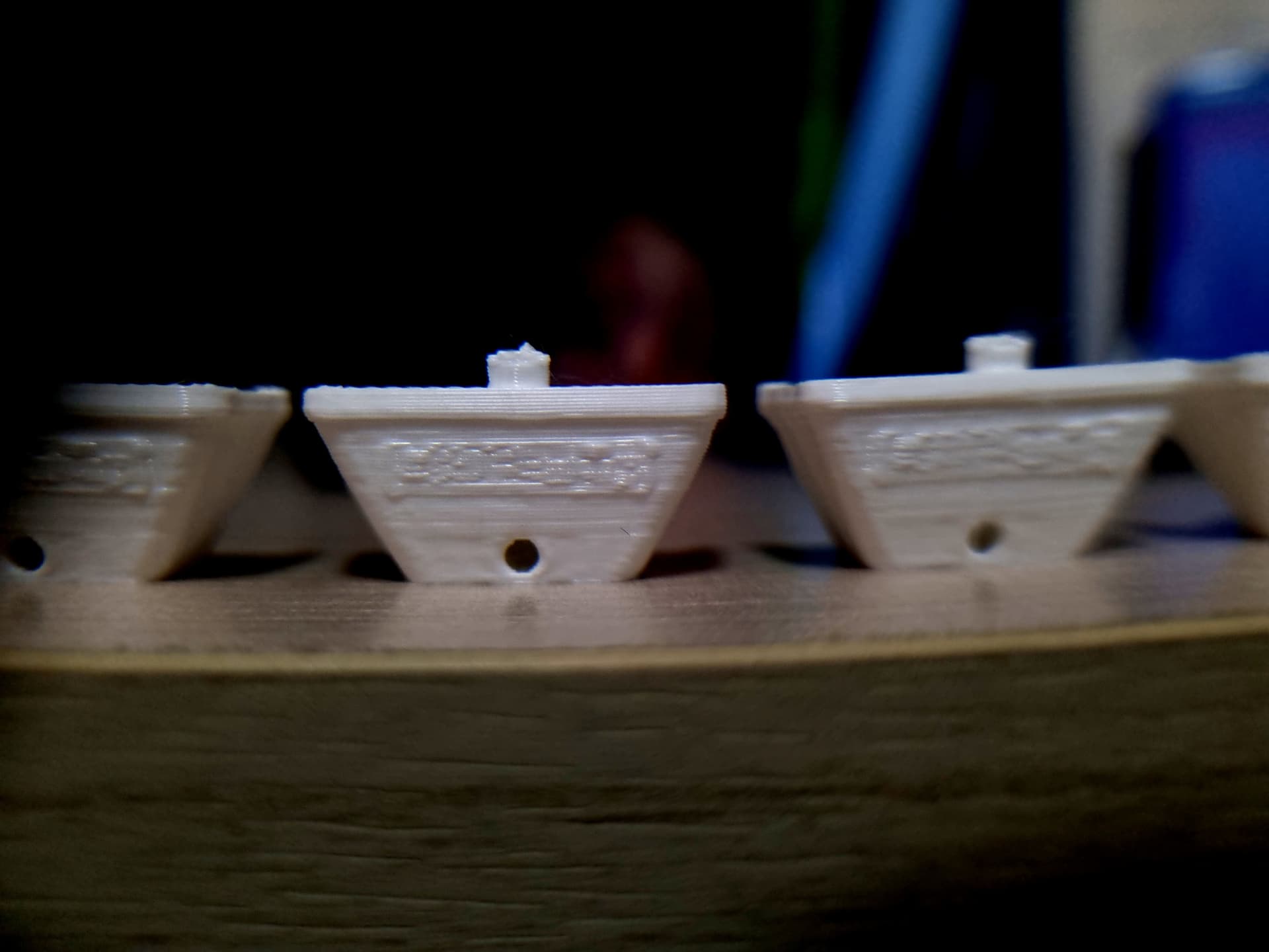
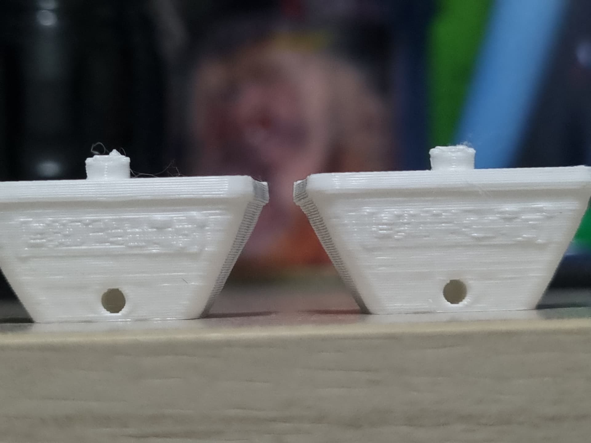
I also got one idea to test this, what if I tested the printer’s ability to print fine details along the axes? And there it is, the text behind benchy:
Even if the details are hard to capture on camera you can see the difference.
I conclude that the X-axis resistance is too high to print very small details. The printer tries to move the print head along the X-axis but the friction is too great and the movement is too small, so the natural elasticity of the belt ends up absorbing that force, moving only along the Y-axis, so we get circles with flat sides or weird bumpiness where there should be fine detail, caused by the forces being released where the details are bigger. You may argue that our circles don’t have perfectly flat sides, but I say that is because the printer enters the X sides of the circles with inertia, making the entrance a little smoother until it loses all of its movement and then with the force accumulated by the elasticity of the belts, bam, it suddenly moves along the X axis with all the accumulated force, creating a step on opposing diagonals of the circle.
For the record, this may be confused with a belt tensioning problem but I’ve learned to differentiate the two as when the problem is caused by wrongly tensioned belts, the speed the printer moves worsens the problem, so it is easy to differentiate as when the inside and outside walls are printed at different speeds, there usually is a separation of the walls of the print such as this example:
In our case where the problem is the resistance of the rods, the speed doesn’t matter, what matters is the size of the circle, the smaller the worse it gets.
I’m currently in contact with Creality support and I will try to get new rods and brass bushings as well.
Hope the collection of information in this post can help other people, thank you @Filamento3D.
Any news? Did Creality support to send you a new X-axis set?
I guess that was just a bad series of rods. I guess they have serial numbers of printers assembled with those rods so that replacement couldn’t be an issue?
Hey, Creality support did send me a new X-axis set BUT unfortunately, that didn’t seem to be the cause of my issue. Currently, I’m still figuring out what to do, maybe there is a clue in this.
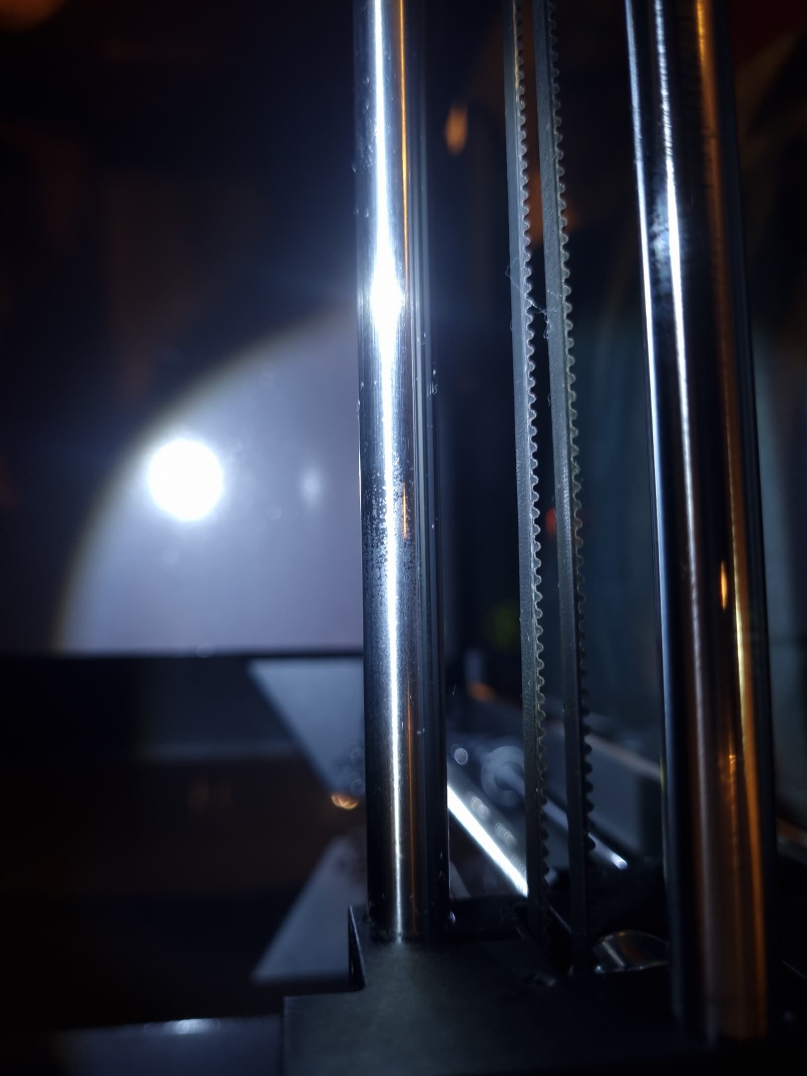
This is my printer running a macro I created to just run the print head side to side on the X-axis, for some reason even if it’s only supposed to move on the X-axis there is some movement in the Y-axis. This only happens on the X-axis, running the script for the Y-axis doesn’t cause any movement in the X-axis.
I tried to remove the springs at the very beginning but it did not help for me.
If you read the whole topic, you will see the solution for me.
But I think that those springs are not needed and I don’t know what is their purpose. Because the brass bushing is held by screews on both sides and there is not any place where those springs could make pressure on the X axis??
From what i can make out, and from my experience with this issue, the carriage/runner have the upper bearing seat bore machined out of spec, as the only mechanical reason i can see for the spring is to apply pressure to the bearing to allow for a deviation of tolerance between the spacing of both X axis rails between units and take out any slack due to that.
However for that to be functional, the bearing seat would need have some free play to the bearing, but mine is/was a loosish push fit, up until the last 1% of being inserted at which point it binds up.
On top of that there appears to be a plating issue with the X axis rods, as some people, inc me, have rods that have bad plating that is not smooth.
Creality have just agreed to send out replace X axis parts.
Last night before i got confirmation of getting replacement part, i thought i would take a closer look at the graphite bearings, carriage and slider rods.
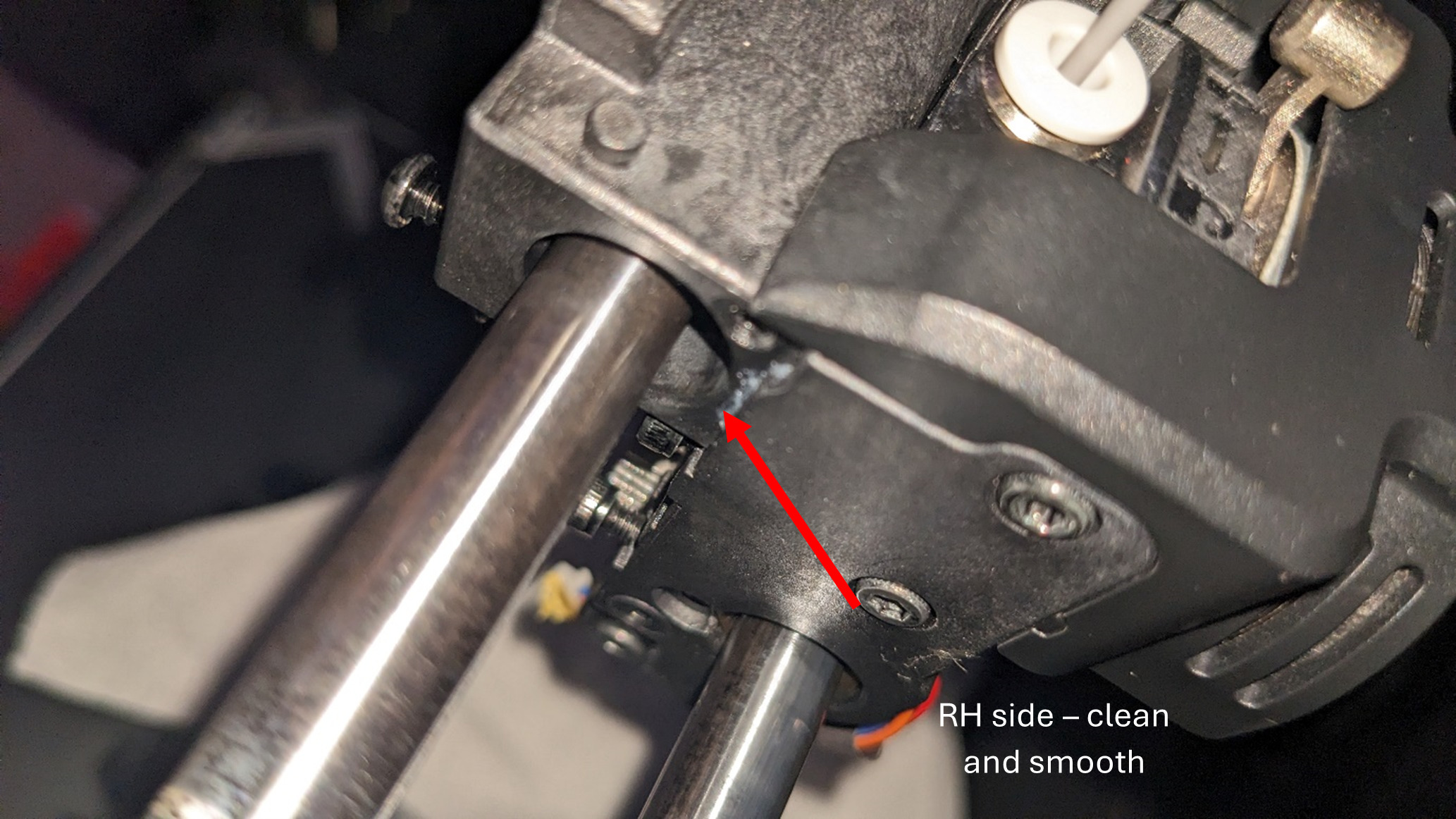
The rods are looking extremely rough under bright light and if you drag your finger nail across the surface you can feel just how rough it is compared to the smooth Y axis.
I was able to fairly easily get the top graphite bearing out of the runner, but the bottom was in there tight and did not want to force it.
As soon as i got the top bearing out, everything freed up. The top bearing would slide just fine and the bottom one and carriage would also move freely.
I noticed from testing that i could slide the bearing in around 99% of the way and the runner was much freer, still not perfect, but functional, yet if i pushed it in that last bit, it would jam up.
On looking into the bore of the bearing seat, the RH side (looking from the front of the unit) was all smooth and nicely machine but the LH side was rougher and had a lip that ran all the way around the circumference, and it was when you pushed the bearing over this lip that it would jam up.
As a temporary measure until i get the parts, i took some fine wet and dry, wetted it, put it around the perimeter of the bushing with an overhang, grit facing outward, using the busing as a form for the wet and dry and spent some time slowly working the ridge flatter, just to the point where it would not bind up when the bushing was fully inserted.
This improved the freeness of the x axis majorly, but is still only temporary until i get the parts to replace the rails and bushings for ones that are not shot.